Scheme-it
Introduction
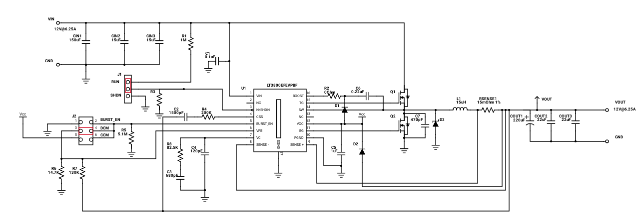
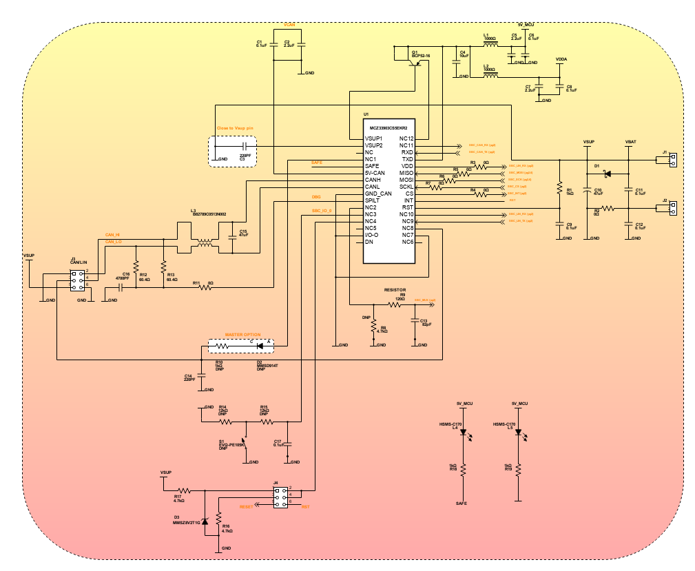
Schematic Drawings

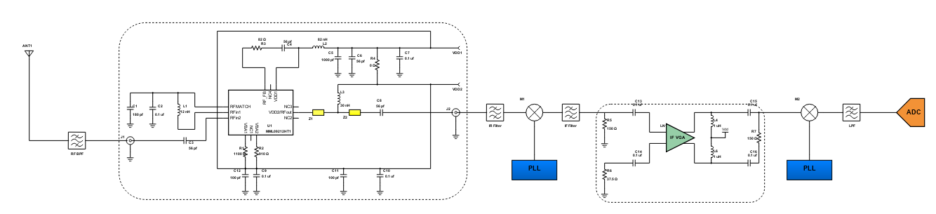
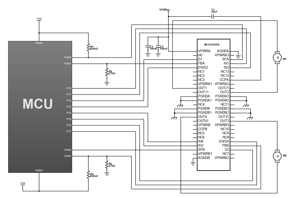
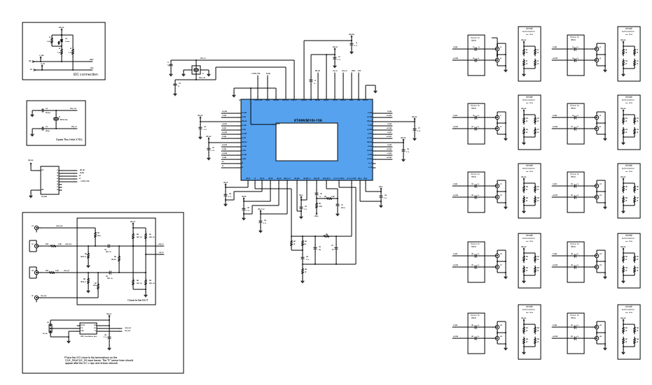
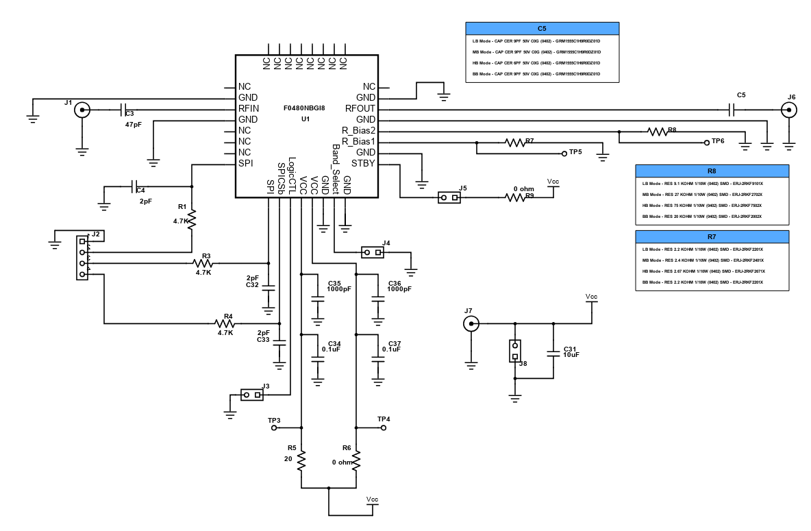
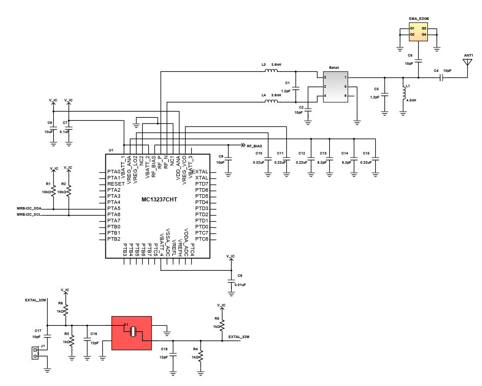
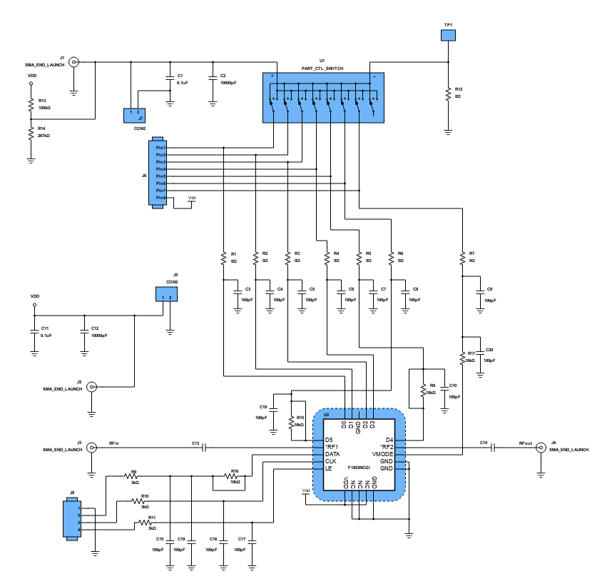
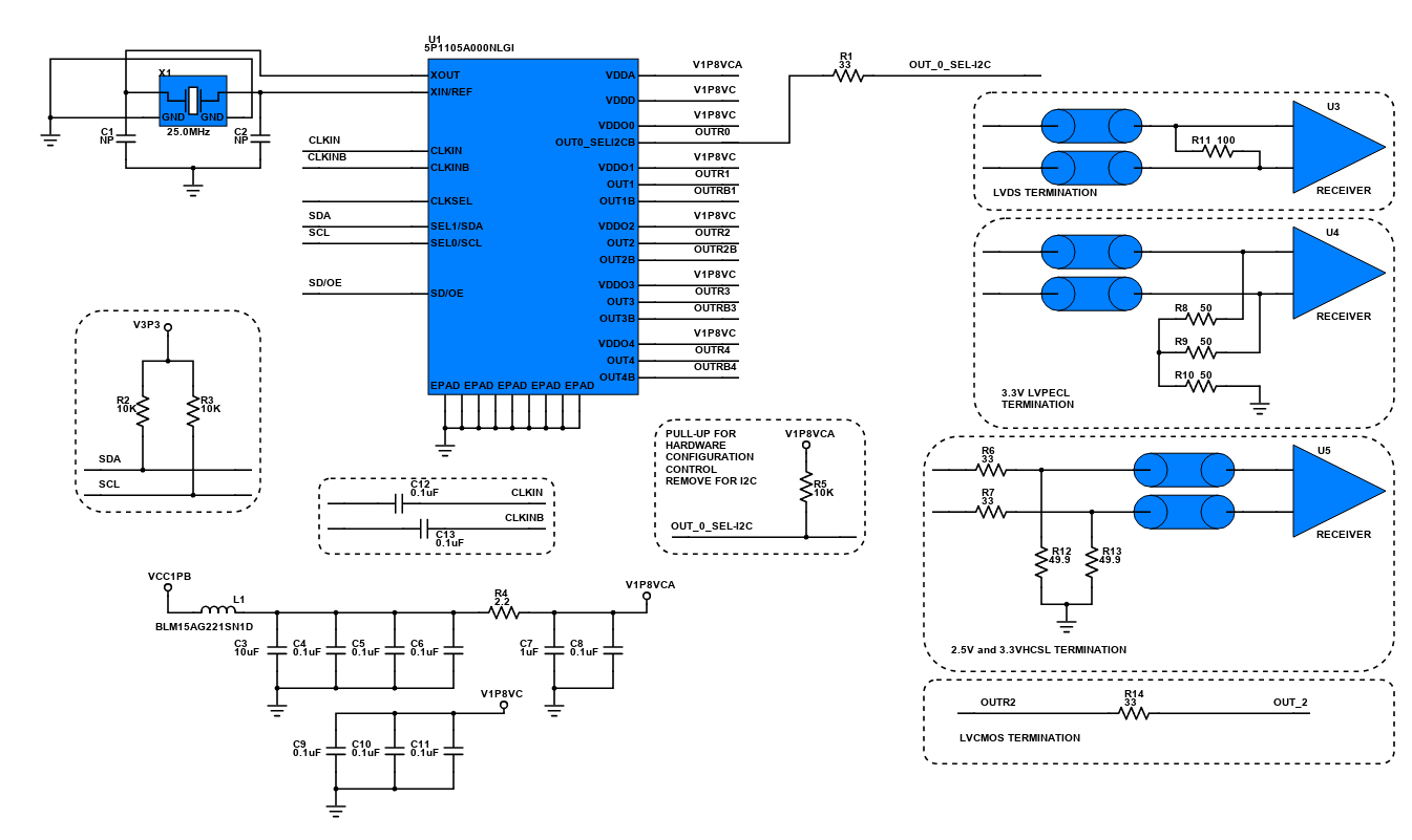
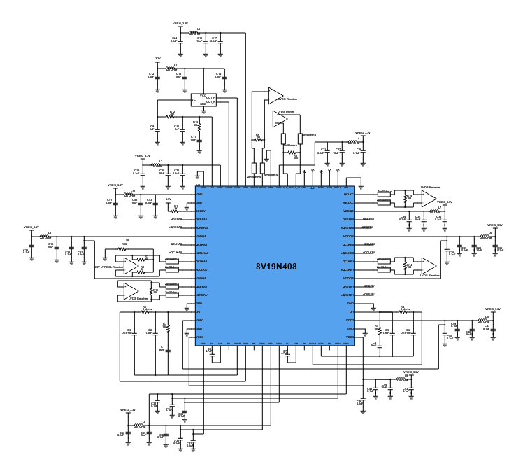
Use schematic symbols to layout the components of your circuit and make electrical connections. With symbols ranging from amplifiers to vacuum tubes, as well as the ability to build custom symbols, you are able to design nearly any circuit. Access to Digi-Key's extensive part database also allows you to browse and assign orderable part numbers.
Diagram Building
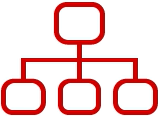
Use the system blocks to refine your idea at a conceptual level. The higher-level components are there to help you plan out the broader intentions of your idea. This powerful block chain library allows you to quickly layout the function of circuit. Once your design is ready, save and share with your colleagues.
Flow Chart Creation
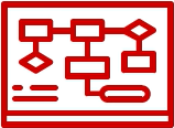
The flow chart creation option will help transition your concept to a design. Use the library of arrows, shapes, UML symbols, and more to sort out the flow and annotate each stage. Insert a textbox, math function/formula, image, or link to help illustrate the objectives and make your plan easy to follow.
Projects
Design Starters help give you a running start for your next design. Whether you are looking to begin a wireless charging platform or quickly design around a Bluetooth Low Energy module, our Design Starters will help get you quickly on your way.
Digi-Key has worked with industry leaders to help drive almost instantaneous ideation and these starters are ideal building blocks to help get your concepts created, drawn and documented in almost no time at all. Featured Design Starters
12 items
Refine Search
APPLICATION
MANUFACTURER
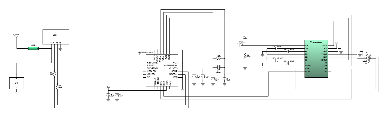
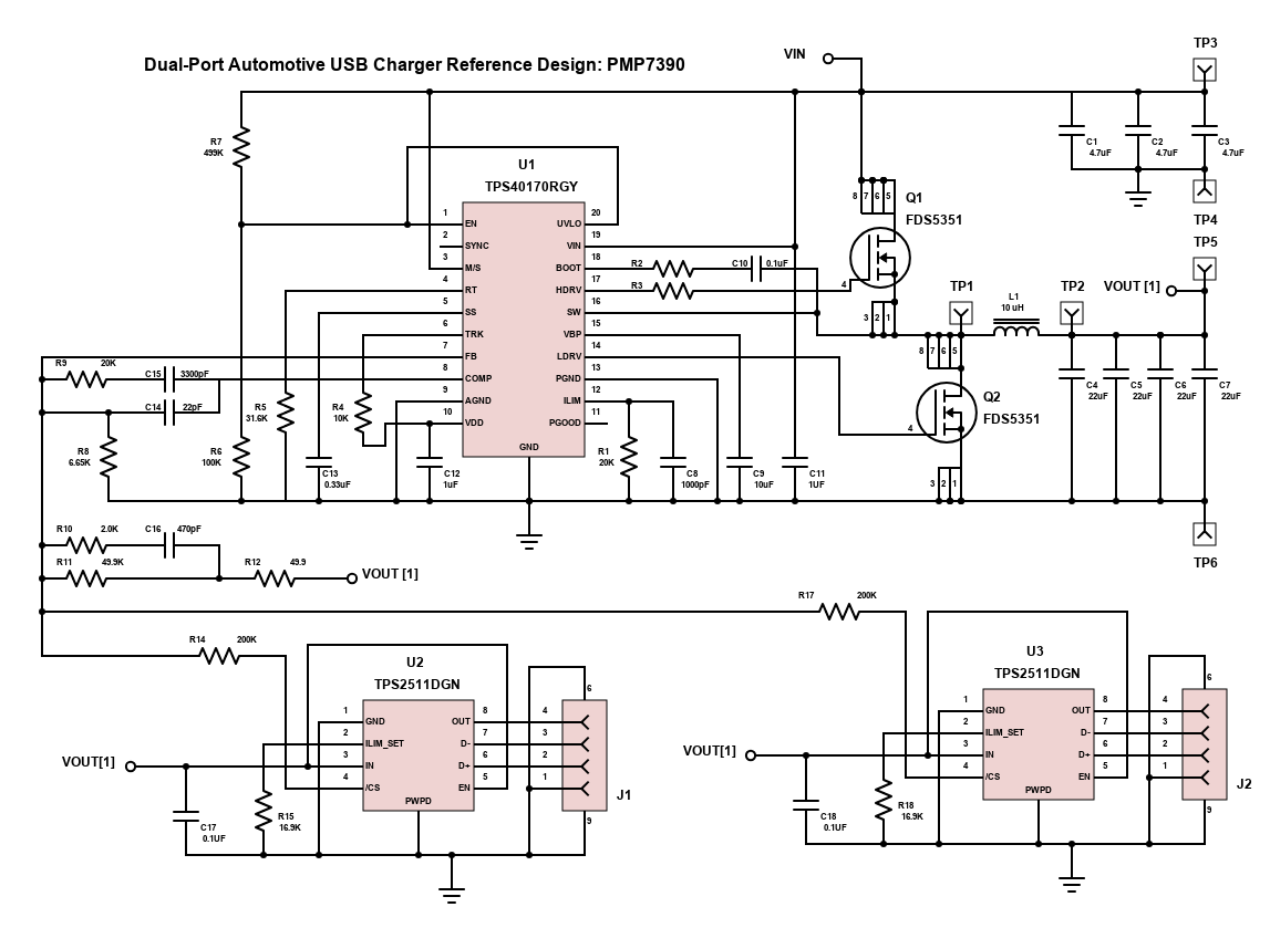
Scheme-it Schematic of Dual Port Auto Charger
The reference design, as shown, is a dual port automotive USB charger from Texas Instruments. This reference design provides a regulated 5V to power 2 USB ports at 2.1A each port in a small form-factor. The design has been optimized for a nominal 12V input and accepts 8V-60V.
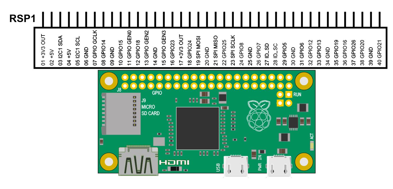
Raspberry Pi Zero
The Raspberry Pi Zero is half the size of a Model A+, with twice the utility. A tiny Raspberry Pi that's affordable enough for any project!
- 1Ghz, Single-core CPU
- 512MB RAM
- Mini HDMI and USB On-The-Go ports
- Micro USB power
- HAT-compatible 40-pin header
- Composite video and reset headers
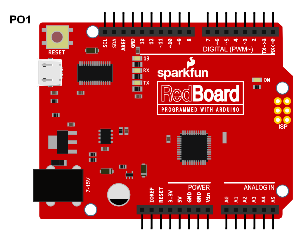
ATMEGA328 FLASHED W/ARDUINO BOOT - DEV-12757
The SparkFun RedBoard combines the simplicity of the UNO's Optiboot bootloader the stability of the FTDI and the R3 shield compatibility of the latest Arduino UNO R3.
- ATmega328 microcontroller with Optiboot (UNO) Bootloader
- USB Programming Facilitated by the Ubiquitous FTDI T231X
- Input voltage - 7-15V
- 0-5V outputs with 3.3V compatible inputs
- 14 Digital I/O Pins (6 PWM outputs)
- 6 Analog Inputs
- ISP Header
- 32k Flash Memory
- 16MHz Clock Speed
- All SMD Construction
- R3 Shield Compatible
- Red PCB!
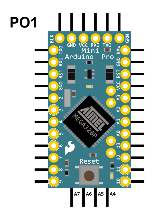
ATMEGA328 ARDUINO PRO MINI 5V - DEV-11113
Arduino Pro Mini is a 5V Arduino running the 16MHz bootloader. Arduino Pro Mini does not come with connectors populated so that user can solder in any connector or wire with any orientation.
- ATmega328 running at 16MHz with external resonator (0.5% tolerance)
- Low-voltage board needs no interfacing circuitry to popular 3.3V devices and modules (GPS, accelerometers, sensors, etc)
- 0.8mm Thin PCB
- USB connection off board
- Weighs less than 2 grams!
- Supports auto-reset
- 5V regulator
- Max 150mA output
- Over current protected
- DC input 3.3V up to 12V
- On board Power and Status LEDs
- Analog Pins: 8
- Digital I/Os: 14

ATMEGA328 ARDUINO PRO MINI 3.3V - DEV-11114
Arduino Pro Mini is a 3.3V Arduino running the 8MHz bootloader. Arduino Pro Mini does not come with connectors populated so that user can solder in any connector or wire with any orientation.
- ATmega328 running at 8MHz with external resonator (0.5% tolerance)
- Low-voltage board needs no interfacing circuitry to popular 3.3V devices and modules (GPS, accelerometers, sensors, etc)
- 0.8mm Thin PCB
- USB connection off board
- Weighs less than 2 grams!
- Supports auto-reset
- 3.3V regulator
- Max 150mA output
- Over current protected
- DC input 3.3V up to 12V
- On board Power and Status LEDs
- Analog Pins: 8
- Digital I/Os: 14
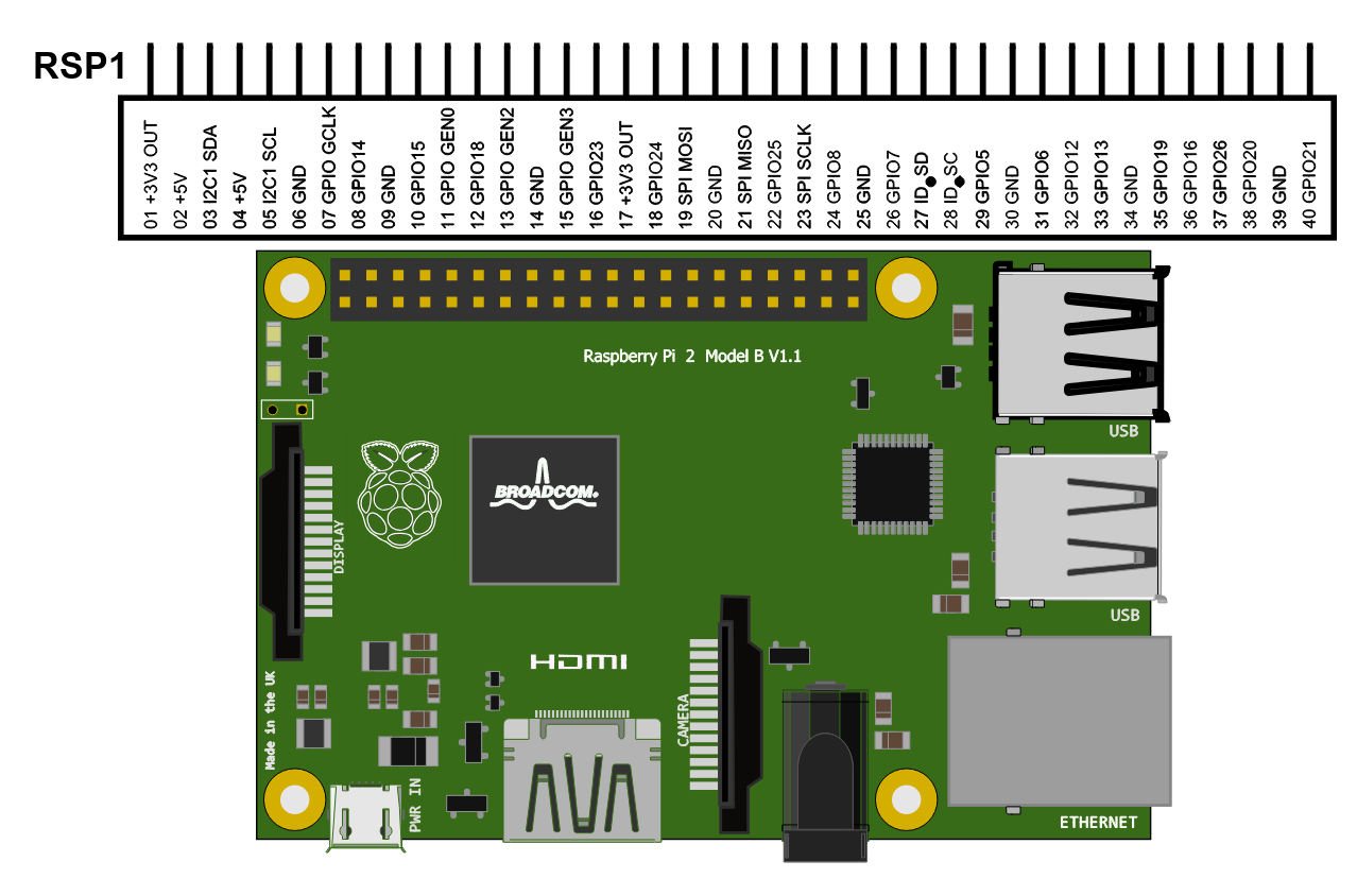
Raspberry Pi 2 Model B
The Raspberry Pi 2 Model B is the second generation Raspberry Pi. It replaced the original Raspberry Pi 1 Model B+ i. Compared to the Raspberry Pi 1 it has:
-A 900MHz quad-core ARM Cortex-A7 CPU
-1GB RAM
Like the (Pi 1) Model B+, it also has:
-4 USB ports
-40 GPIO pins
-Full HDMI port
-Ethernet port
-Combined 3.5mm audio jack and composite video
-Camera interface (CSI)
-Display interface (DSI)
-Micro SD card slot
-VideoCore IV 3D graphics core
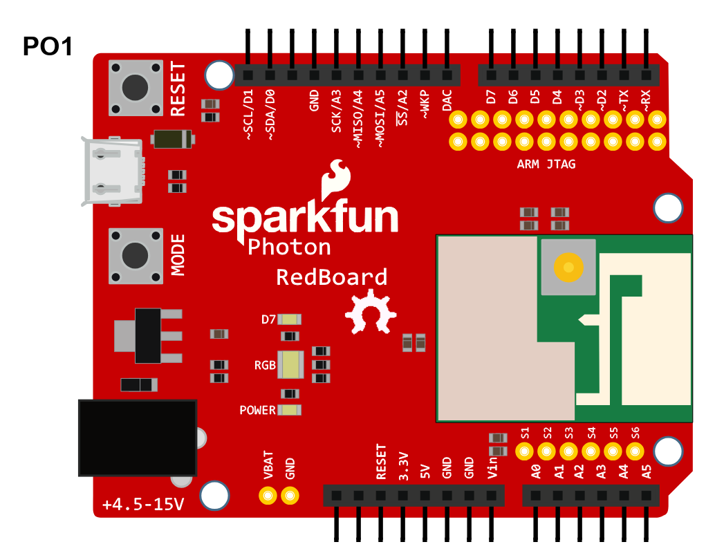
PHOTON REDBOARD - DEV-13321
The SparkFun Photon RedBoard, to put it simply, is a WiFi/Microcontroller development board in the Arduino form-factor for the Photon. It's easy to use, it's powerful, and it's connected to the cloud. With the best support, potential, and performance the Photon RedBoard provides you with an IoT device with a powerful 120MHz ARM Cortex M3 and built-in WiFi connectivity.
-STM32F205 120MHz ARM Cortex M3
-1MB flash, 128KB RAM
-Single band 2.4GHz IEEE 802.11b/g/n
-Supports wireless data rates of up to 65Mbit/s
-Ultra low power sleep, stand-by and stop modes
-Supports Open, WEP, WAPI, WPA and WPA2-PSK WiFi security modes
-Input voltage - 4.5-15V
-8 Digital I/O Pins
-6 Analog Inputs
-ARM JTAG Hook-up
-Arduino Form Factor
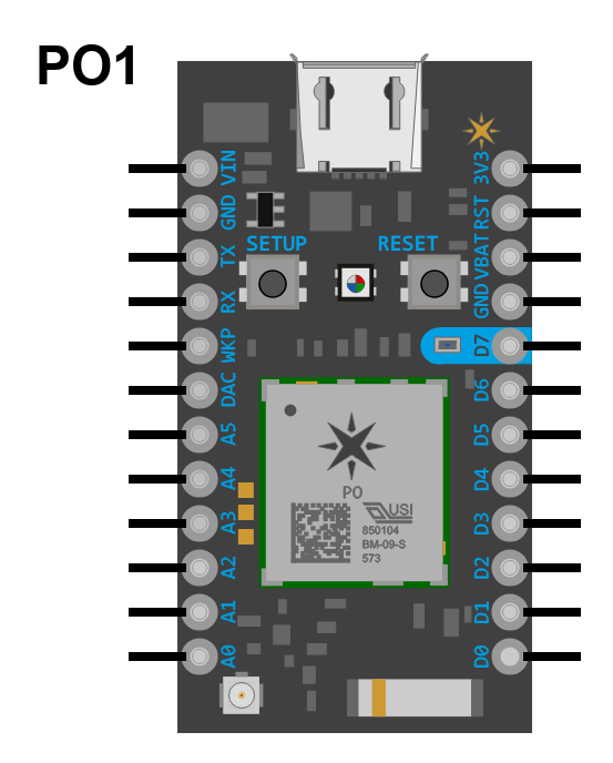
PARTICLE PHOTON - WRL-13764
Particle's IoT (Internet of Things) hardware development board, the Photon, provides everything needed to build a connected project. Particle has combined a powerful microcontroller with a Wi-Fi chip in a tiny thumbnail-sized module called the PØ (P-Zero).
-Particle PØ Wi-Fi module
-Broadcom BCM43362 Wi-Fi chip
-802.11b/g/n Wi-Fi
-STM32F205 120Mhz ARM Cortex M3
-1MB flash, 128KB RAM
-On-board RGB status LED (ext. drive provided)
-18 Mixed-signal GPIO and advanced peripherals
-Open source design
-Real-time operating system (FreeRTOS)
-Soft AP setup
-FCC, CE, and IC certified
-No Headers Included
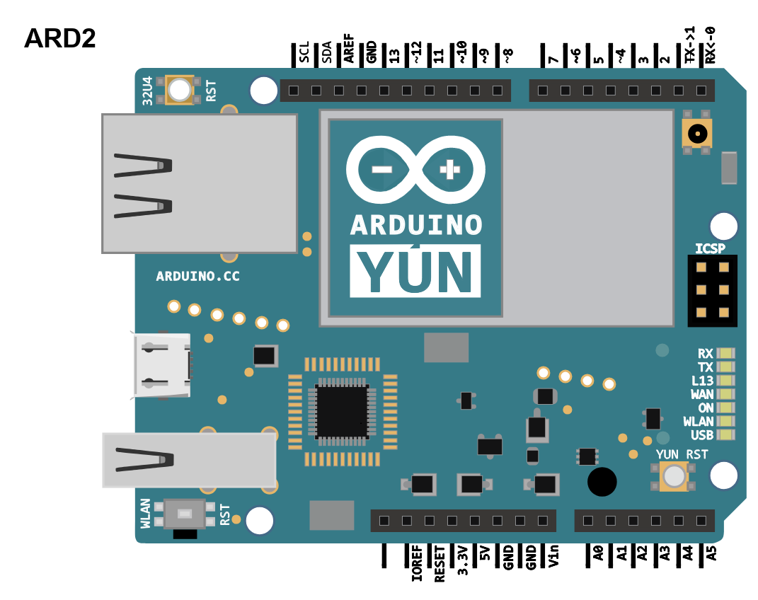
ARDUINO YUN - A000008
The Arduino Yun is a board based on ATmega32u4 microcontroller and Atheros AR9331 processor. The ATmega32u4 is a low-power 8-bit AVR RISC-based microcontroller featuring 32KB self-programming flash program memory, 2.5KB SRAM, 1KB EEPROM, USB 2.0 full-speed/low speed device, 12-channel 10-bit A/D-converter, and JTAG interface for on-chip-debug. On the other hand, the Atheros processor supports a Linux distribution based on OpenWrt named Linino OS.
The board has the following built-in features:
• Ethernet and WiFi support
• a USB-A port
• micro-SD card slot
• 20 digital input/output pins (7 of them can be used as PWM outputs and 12 as analog inputs),
• a 16 MHz crystal oscillator
• a micro USB connection
• an ICSP header
• 3 reset buttons
HUZZAH ESP8266 Breakout - 2471
This board is a Adafruit HUZZAH ESP8266 breakout, which uses the ESP8266 processor from Espressif. This processor is an 80 MHz microcontroller with a full WiFi front-end (both as client and access point) and TCP/IP stack with DNS support as well. While this chip has been very popular, it's also been very difficult to use. Most of the low cost modules are not breadboard friendly, don't have an onboard 500mA 3.3V regulator or level shifting, and aren't CE or FCC emitter certified. This board comes with a bite-sized WiFi controller at an affordable price. A certified antenna module with an onboard antenna, and plenty of pins, and soldered it onto the designed breakout PCBs. Some additional features are the following:
• Reset button
• User button that can also put the chip into bootloading mode,
• Red LED you can blink
• Level shifting on the UART and reset pin
• 3.3V out, 500mA regulator (you'll want to assume the ESP8266 can draw up to 250mA so budget accordingly)
• Two diode-protected power inputs (one for a USB cable, another for a battery)
Two parallel, breadboard-friendly breakouts on either side give you access to:
• 1 x Analog input (1.0V max)
• 9 x GPIO (3.3V logic), which can also be used for I2C or SPI
• 2 x UART pins
• 2 x 3-6V power inputs, reset, enable, LDO-disable, 3.3V output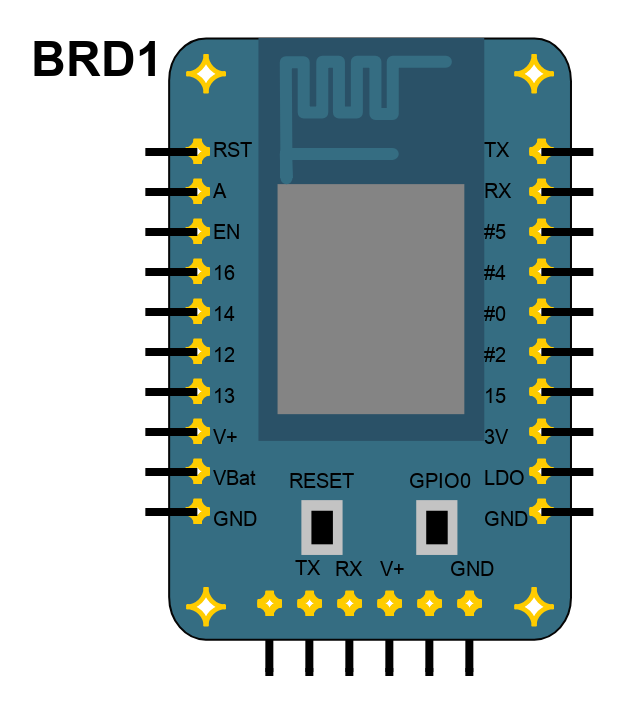
Introduction
Schematic Drawings
Use schematic symbols to layout the components of your circuit and make electrical connections. With symbols ranging from amplifiers to vacuum tubes, as well as the ability to build custom symbols, you are able to design nearly any circuit. Access to Digi-Key's extensive part database also allows you to browse and assign orderable part numbers.
Diagram Building
Use the system blocks to refine your idea at a conceptual level. The higher-level components are there to help you plan out the broader intentions of your idea. This powerful block chain library allows you to quickly layout the function of circuit. Once your design is ready, save and share with your colleagues.
Flow Chart Creation
The flow chart creation option will help transition your concept to a design. Use the library of arrows, shapes, UML symbols, and more to sort out the flow and annotate each stage. Insert a textbox, math function/formula, image, or link to help illustrate the objectives and make your plan easy to follow.
Help & Resources
Need help? Ask questions in our TechForum

Conversion Calculators
Digi-Key's online conversion calculators offer a one-stop resource for many electronics industry calculations.
Go to Calculators
Conversion Calculators
Digi-Key's online conversion calculators offer a one-stop resource for many electronics industry calculations.
Go to Calculators

Reference Design Library
Search for designs based on the circuit's performance using Digi-Key's Reference Design Library.
Go to Reference Design Library
Reference Design Library
Search for designs based on the circuit's performance using Digi-Key's Reference Design Library.
Go to Reference Design Library
Tech Forum
Feedback
You are about to delete project
Please type 'DELETE' (without quotes) to the below box to confirm the deletion: