Scheme-it
Introduction
Schematic Drawings

Use schematic symbols to layout the components of your circuit and make electrical connections. With symbols ranging from amplifiers to vacuum tubes, as well as the ability to build custom symbols, you are able to design nearly any circuit. Access to Digi-Key's extensive part database also allows you to browse and assign orderable part numbers.
Diagram Building

Use the system blocks to refine your idea at a conceptual level. The higher-level components are there to help you plan out the broader intentions of your idea. This powerful block chain library allows you to quickly layout the function of circuit. Once your design is ready, save and share with your colleagues.
Flow Chart Creation
The flow chart creation option will help transition your concept to a design. Use the library of arrows, shapes, UML symbols, and more to sort out the flow and annotate each stage. Insert a textbox, math function/formula, image, or link to help illustrate the objectives and make your plan easy to follow.
Projects
Design Starters help give you a running start for your next design. Whether you are looking to begin a wireless charging platform or quickly design around a Bluetooth Low Energy module, our Design Starters will help get you quickly on your way.
Digi-Key has worked with industry leaders to help drive almost instantaneous ideation and these starters are ideal building blocks to help get your concepts created, drawn and documented in almost no time at all. Featured Design Starters
12 items
Refine Search
APPLICATION
MANUFACTURER
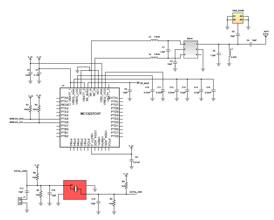
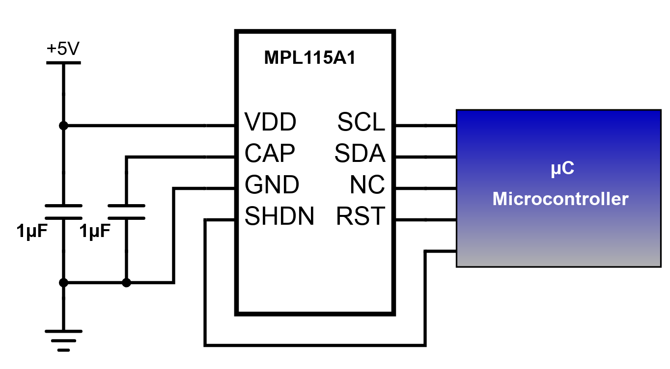
Simple Digital Barometer
The digital barometer reading is a new concept that replaces traditional analog barometer . A barometer is an integral part of meteorology in order to measure climatic pressure. Pressure tendency can forecast transient changes in the climate. Various estimations of air pressure are utilized within surface climate analysis to help discover surface troughs, high pressure frameworks and frontal limits. It has digitized pressure and temperature information together with programmed calibration coefficients for host microcontroller use.
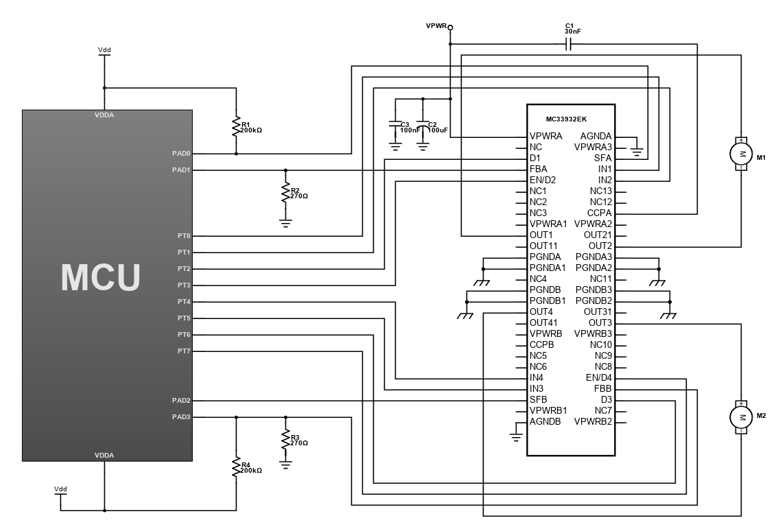
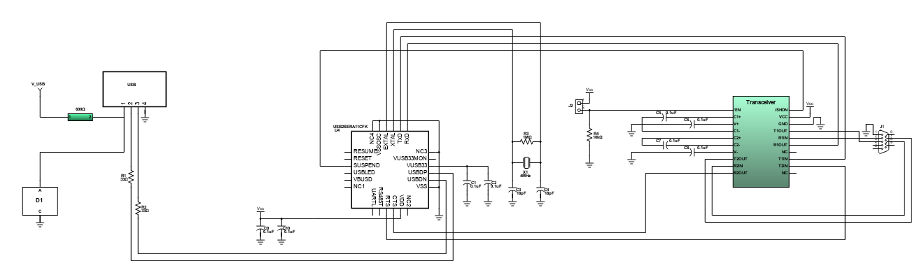
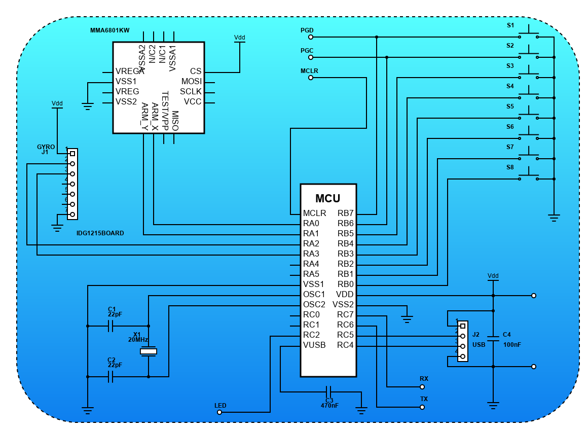
Accelerometer Controlled USB Gamepad
This design demonstrates an accelerometer controlled USB gamepad that supports up to 8 buttons using freescale's MMA6801KW. In this game controller, you can actually use the FORWARD/BACK tilt (Y axis of the device), besides the usual LEFT/RIGHT (X axis). The code for the firmware was written in PicBasic Pro and it implements a HID USB device with 2-axis gyroscope and a 2-axis accelerometer. It has a built in voltage regulator, which allows powering the accelerometer directly from the USB bus (5V).
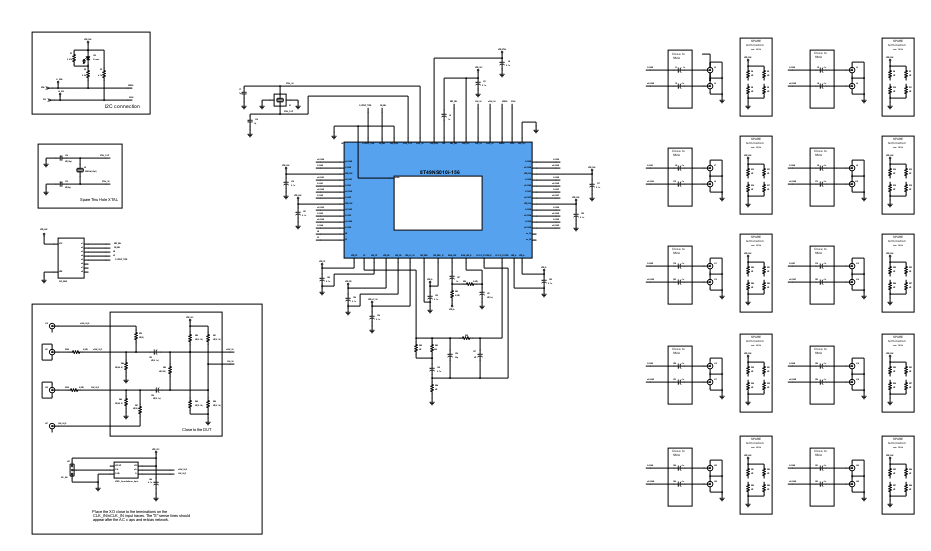
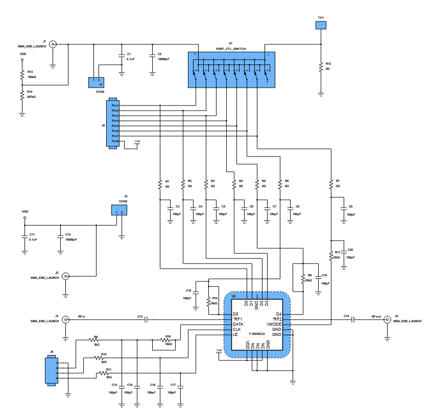
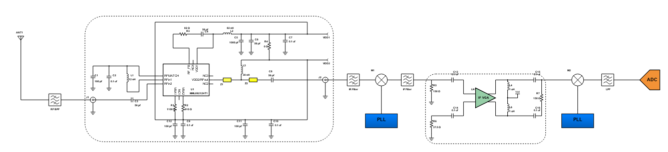
400 - 1400 Mhz Wireless Radio Receiver
Wireless communications had been through many innovations since it was first developed and implemented a long time ago. Many techniques had also been used to fit different applications and meet the changing standards of communication as the time passes by. In this design, a typical diagram of a wireless receiver which is often associated with the superheterodyne architecture is shown. It is mainly comprised of an antenna , filters, Low Noise Amplifier (LNA), mixers. Variable Gain Amplifier (VGA) and an Analog-to-Digital Converter (ADC).
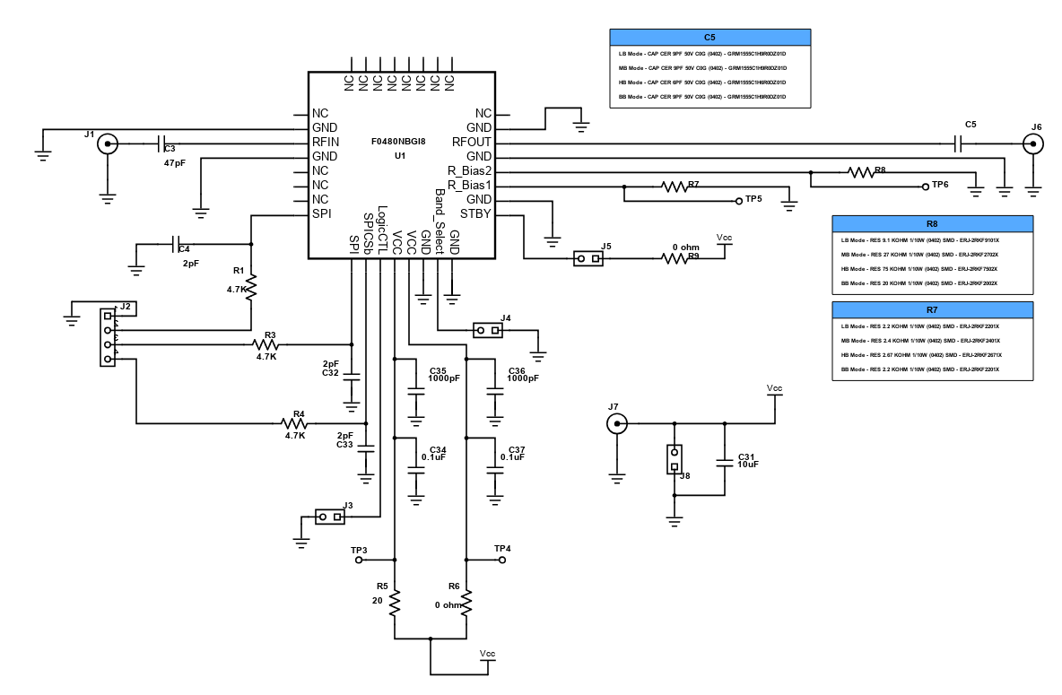
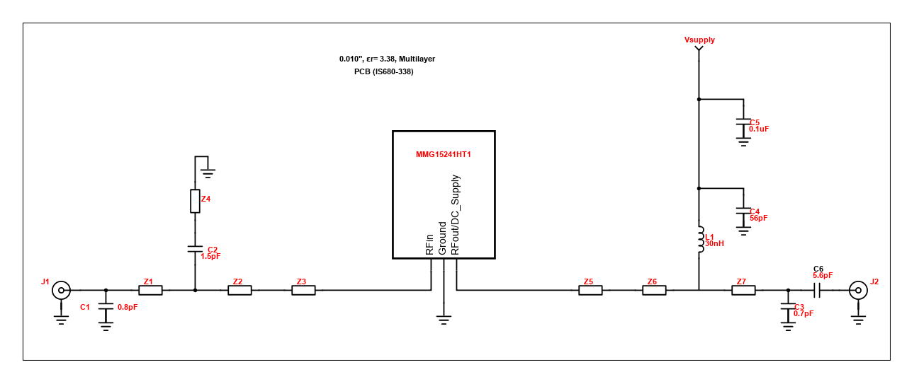
2140 MHz Low Noise Amplifier Monolithic Microwave Integrated Circuits(MMIC)
The RF driver amplifier and LNA are important parts in order to attain an efficient RF signal transmission and reception. In communication, these components are located near the antenna, which amplifies the RF signal before transmission (for RF driver amplifier) and amplifies weak signal in the reception (for LNA). This simple design and test circuit features pHEMT or pseudomorphic High-Electron-Mobility Transistor technology of LNA MMIC for RF transceivers. It provides a 1.6dB noise figure with third order output intercept point that is 39.4dBm at 2140MHz frequency. With its significant features, it ensures that the amplifications of weak signals will have lesser noise compared to a regular amplifier.
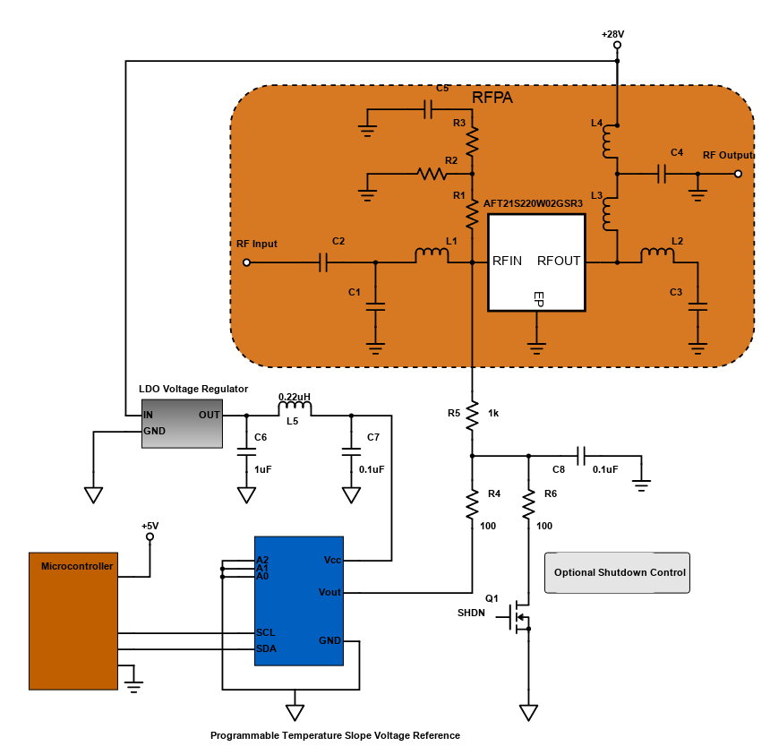
LDMOS Transistor Bias Control in RF Power Amplifiers
Nowadays, laterally diffused metal oxide semiconductor (LDMOS) transistors are widely used for RF Power Amplification and in many applications. A simplified circuit of an LDMOS amplifier bias circuit is shown in the schematic diagram above. The DC Bias on these amplifiers is set by applying a DC voltage to the gate (VGS) and by monitoring the Drain current (IDD). Ideally, this IDD will be constant over temperature, but since the VGS of LDMOS amplifier devices varies with temperature, some type of temperature compensation is required.
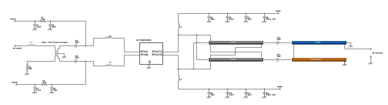
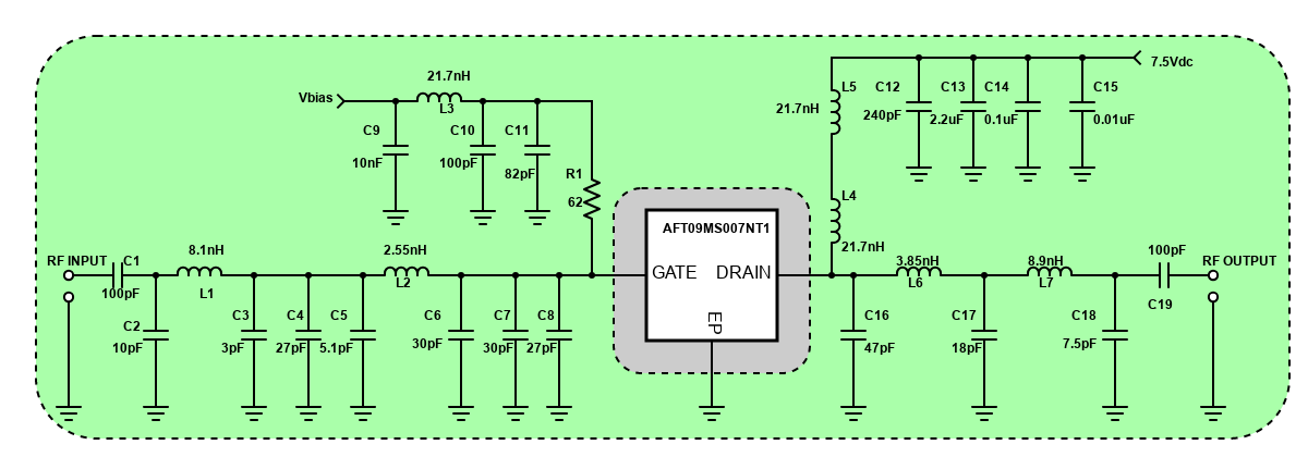
2100MHz RF Power Amplifier for International Mobile Telecommunications
Our telecommunication data usage is rapidly increasing in which Internet Service Providers (ISPs) are having difficulties in managing the demand of their customers. This problem is caused by the number of people that are now into digital communications, which smartphones provide them access to the internet anywhere they want as long as there is a GSM signal. This design features an RF Power LDMOS Transistor that is used in 2100MHz RF Power Amplifier. The 2100MHz frequency band is a WCDMA air interface standard, which is also a basis of Universal Mobile Telecommunications System (UMTS). It has digital predistortion error correction system and great negative gate-source voltage range for improved class C operation that are good for cellular base station applications.
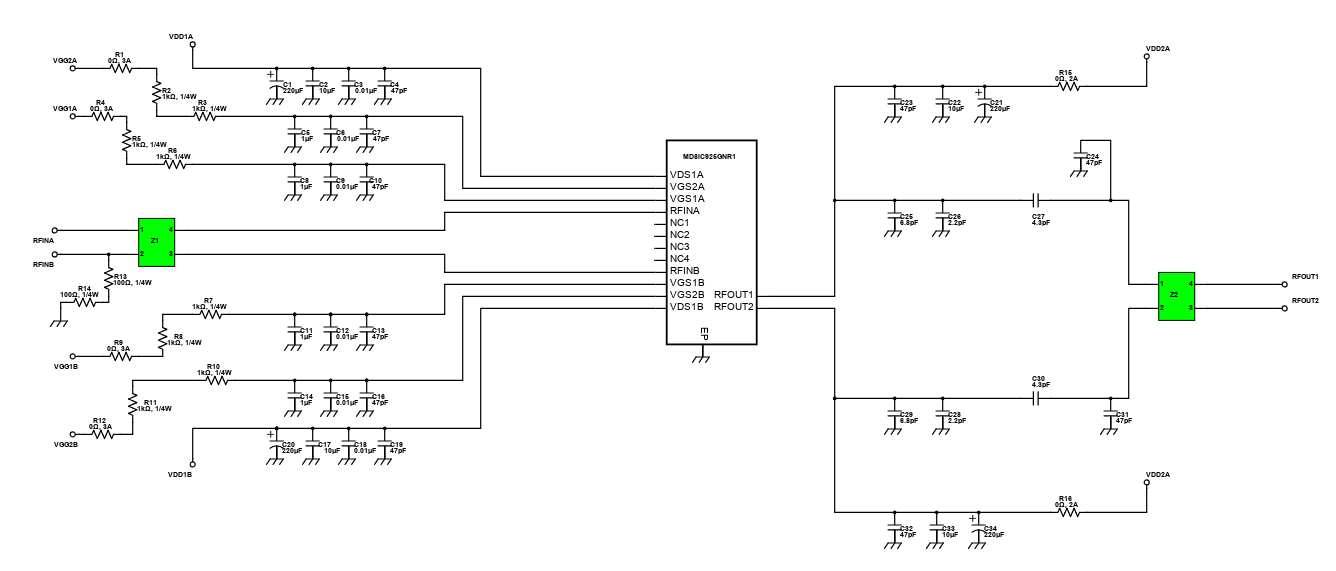
RF Downlink LDMOS Wideband Power Amplifier
The increase of mobile phone user produces a bigger demand in Global System for Mobile communications (GSM) in which satellite transmitters and other type of telecommunication entities are now expanding to meet the demand. These transmitters make use of RF power amplifiers that convert the low power radio-frequency signal into a larger signal of significant power. It has on-chip matching that makes it usable from 728 to 960MHz frequency and multi-stage structure is rated 24V to 32V operation that also covers all typical cellular base station modulation formats. It is also design for digital predistortion error correction systems and optimized for doherty applications.
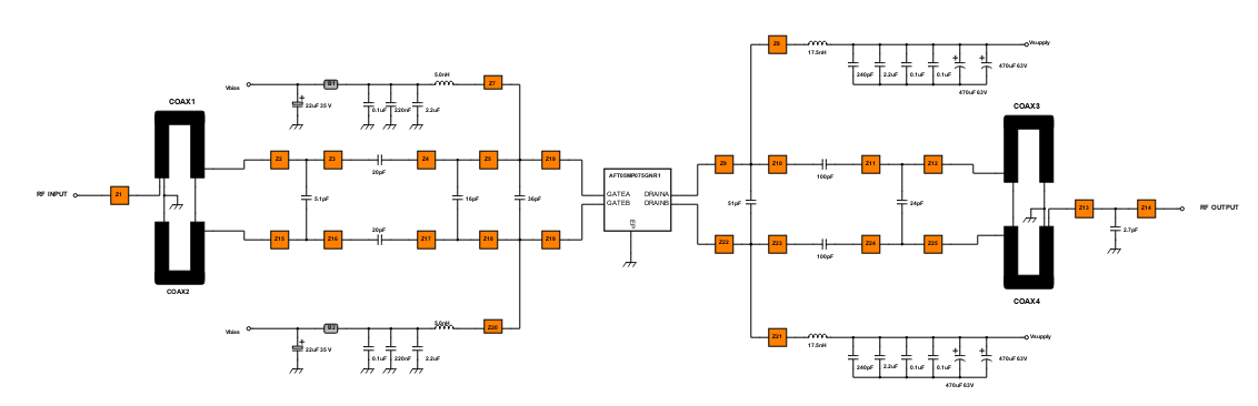
AFT05MP075GNR1 Narrowband RF Power Amplifier (520MHz)
The RF power amplifier stage is usually the final active block of any electronic system that is transmitting RF power. Relatively low power RF signals are amplified to produce a more powerful signal in order to be transmitted over greater distance. RF output power can range from a few mW to MW, depend by application. RF amplifiers before were all made using vacuum tubes but modern RF amplifier nowadays uses solid state devices like MOSFET, TMOS-FET, Bipolar junction transistors, and IGBT to amplify RF signals.
UHF Power Amplifier for Professional Mobile Radio
Professional Mobile Radio, commonly known as Private Mobile Radio (PMR), is a portable, mobile base station, which provides two-way mobile radio communications. These systems were only able to communicate over relatively short distances. They used a single central base station to communicate with all the mobile stations. This considerably reduced their coverage area. To overcome this a system, known as trunking, was devised whereby several transmitters could be used and the signal was trunked to the correct station.
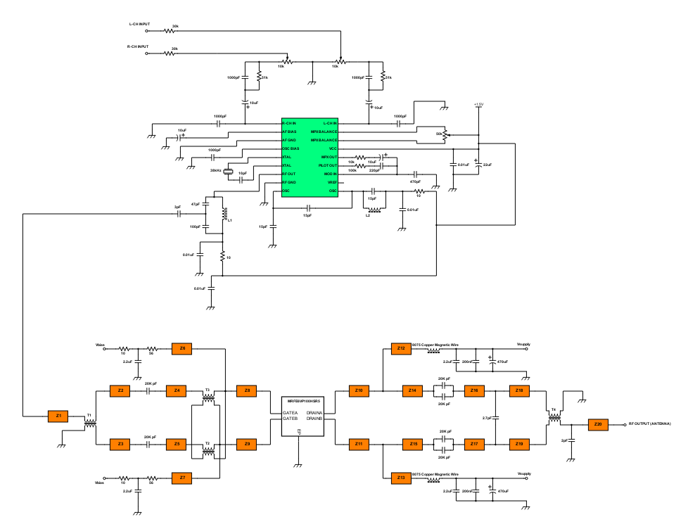
100 Watts Stereo FM Transmitter
Creating a HI-FI stereo FM transmitter to transmit music around the house or even for your own radio station can be sometimes really challenging. Designing preamplifiers, buffers, RF oscillators, modulators, and RF amplifiers add to the difficulty of building an FM transmitter. With this circuit, we can minimize the complexity of creating stereo FM transmitters.
Introduction
Schematic Drawings
Use schematic symbols to layout the components of your circuit and make electrical connections. With symbols ranging from amplifiers to vacuum tubes, as well as the ability to build custom symbols, you are able to design nearly any circuit. Access to Digi-Key's extensive part database also allows you to browse and assign orderable part numbers.
Diagram Building
Use the system blocks to refine your idea at a conceptual level. The higher-level components are there to help you plan out the broader intentions of your idea. This powerful block chain library allows you to quickly layout the function of circuit. Once your design is ready, save and share with your colleagues.
Flow Chart Creation
The flow chart creation option will help transition your concept to a design. Use the library of arrows, shapes, UML symbols, and more to sort out the flow and annotate each stage. Insert a textbox, math function/formula, image, or link to help illustrate the objectives and make your plan easy to follow.
Help & Resources
Need help? Ask questions in our TechForum

Conversion Calculators
Digi-Key's online conversion calculators offer a one-stop resource for many electronics industry calculations.
Go to Calculators
Conversion Calculators
Digi-Key's online conversion calculators offer a one-stop resource for many electronics industry calculations.
Go to Calculators

Reference Design Library
Search for designs based on the circuit's performance using Digi-Key's Reference Design Library.
Go to Reference Design Library
Reference Design Library
Search for designs based on the circuit's performance using Digi-Key's Reference Design Library.
Go to Reference Design Library
Tech Forum
Feedback
You are about to delete project
Please type 'DELETE' (without quotes) to the below box to confirm the deletion: