Scheme-it
Introduction
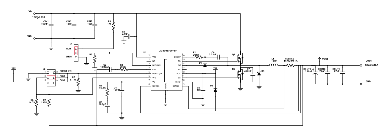
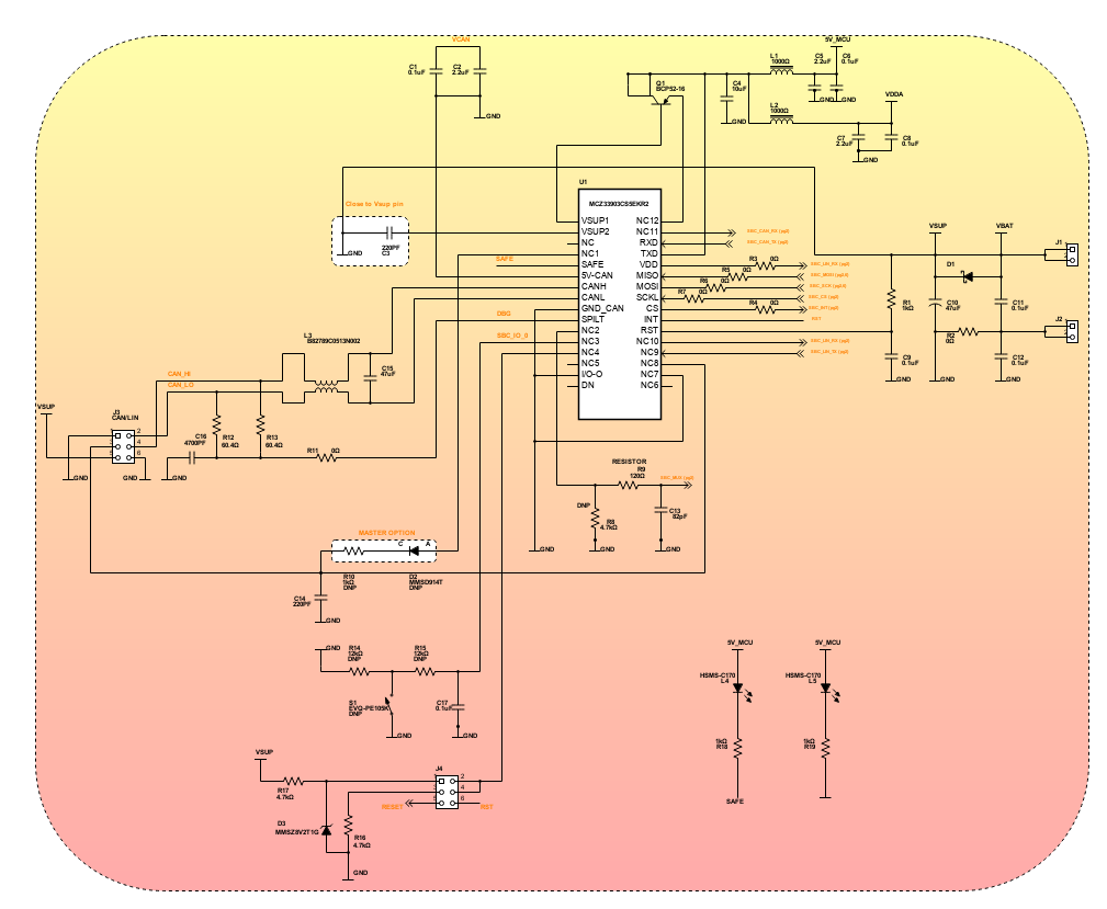
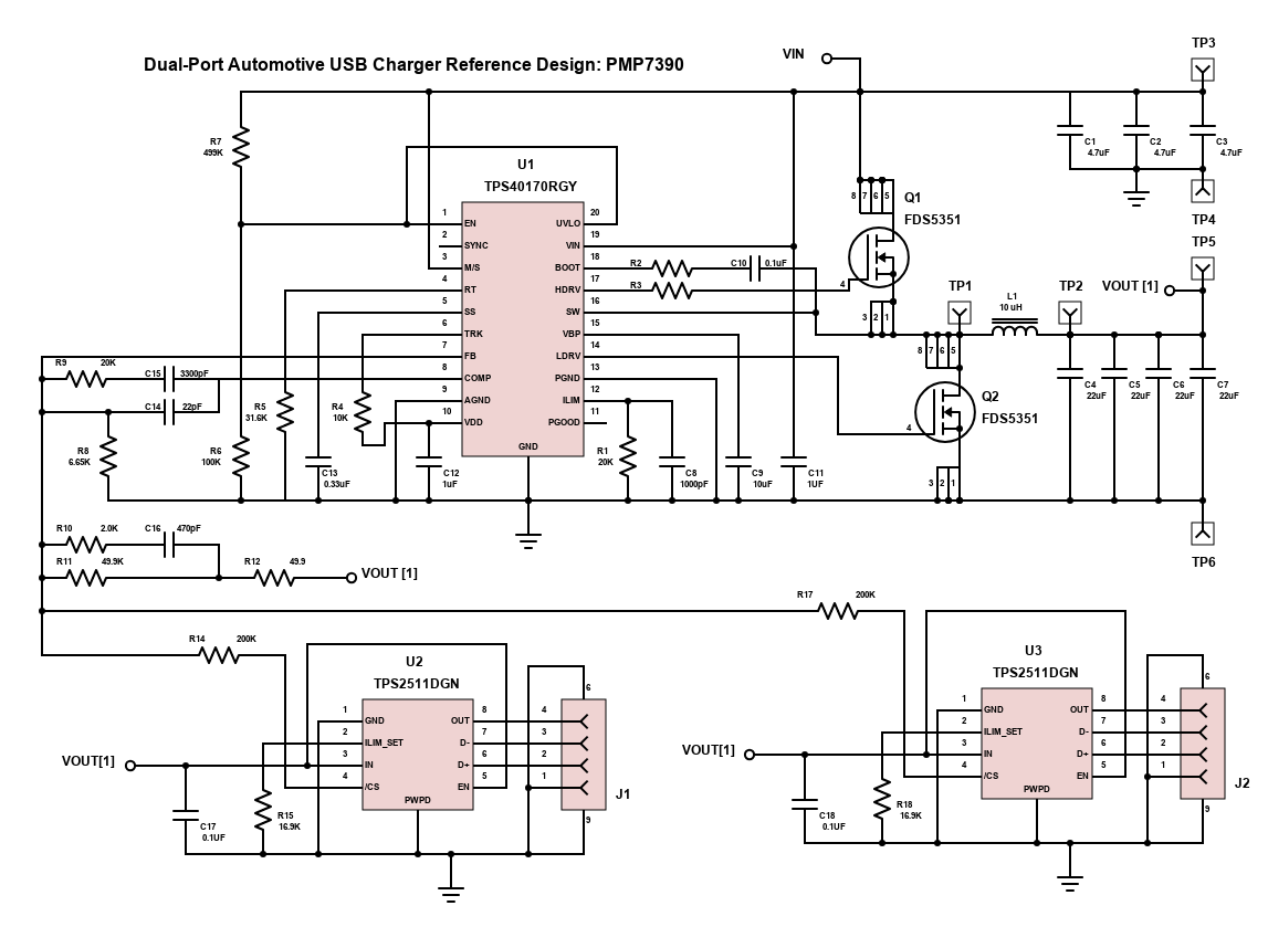
Schematic Drawings

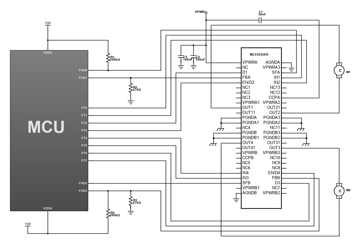
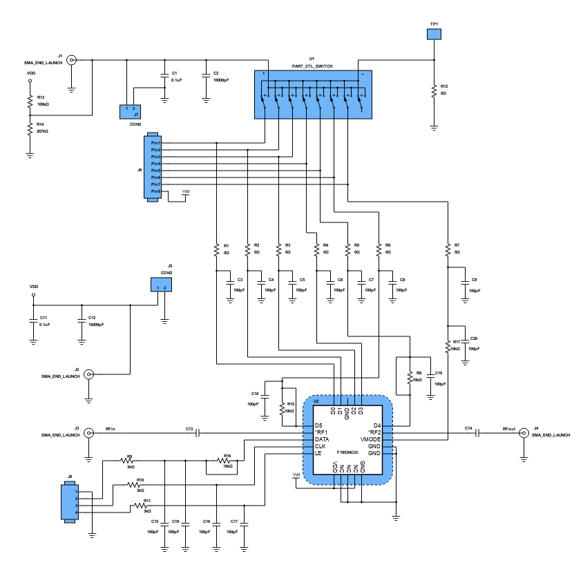
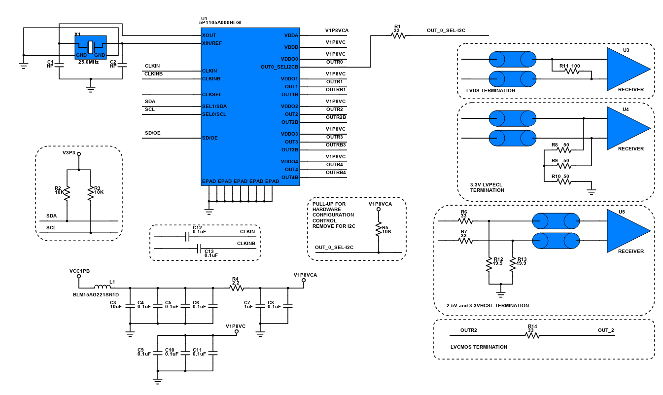
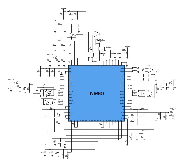
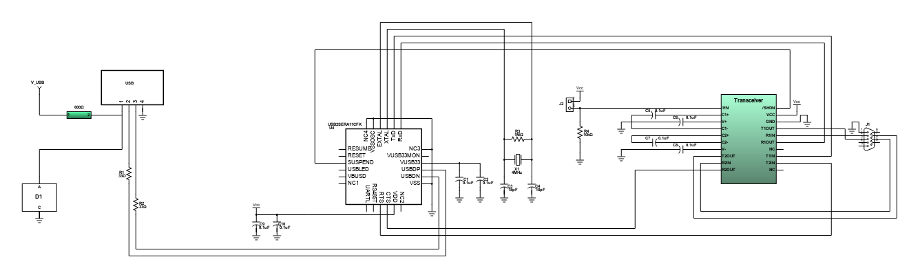
Use schematic symbols to layout the components of your circuit and make electrical connections. With symbols ranging from amplifiers to vacuum tubes, as well as the ability to build custom symbols, you are able to design nearly any circuit. Access to Digi-Key's extensive part database also allows you to browse and assign orderable part numbers.
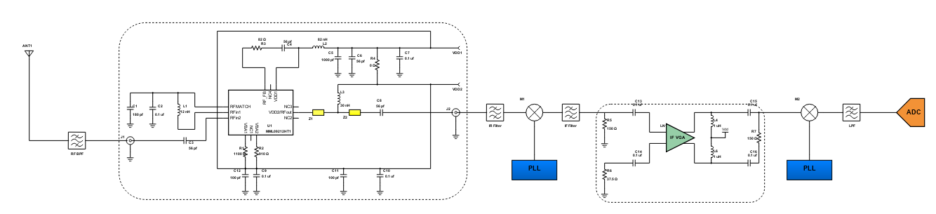
Diagram Building

Use the system blocks to refine your idea at a conceptual level. The higher-level components are there to help you plan out the broader intentions of your idea. This powerful block chain library allows you to quickly layout the function of circuit. Once your design is ready, save and share with your colleagues.
Flow Chart Creation

The flow chart creation option will help transition your concept to a design. Use the library of arrows, shapes, UML symbols, and more to sort out the flow and annotate each stage. Insert a textbox, math function/formula, image, or link to help illustrate the objectives and make your plan easy to follow.
Projects
Design Starters help give you a running start for your next design. Whether you are looking to begin a wireless charging platform or quickly design around a Bluetooth Low Energy module, our Design Starters will help get you quickly on your way.
Digi-Key has worked with industry leaders to help drive almost instantaneous ideation and these starters are ideal building blocks to help get your concepts created, drawn and documented in almost no time at all. Featured Design Starters
12 items
Refine Search
APPLICATION
MANUFACTURER
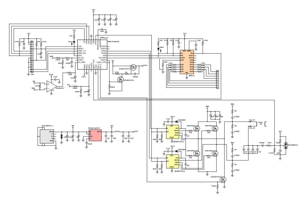
Wireless Transmitter System
This project is a wireless power transmission system that works on the principle of magnetic induction. This wireless charging system works as the digital switched mode power supply with the transformer, which is separated into two parts: The transformer primary coil works as the transmitter coil, and the transformer secondary coil serves as the receiver. This system works based on magnetic induction, the better coupling between the transmitter coil and receiver coil gain, the better system efficiency. So the receiver coil should be closely and center-aligned with the transmitter coil as possible. After the receiver coil receives the power from the transmitter coil by magnetic field, it regulates the received voltage to power the load, and send its operational information to transmitter according to specific protocol by the communication link. Then the system can achieve the closed-loop control, and power the load stably and wirelessly.
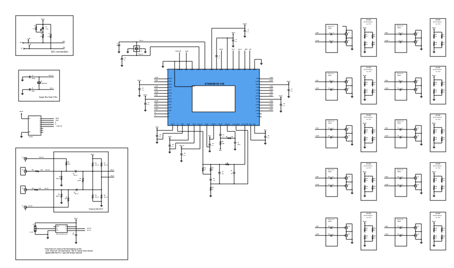
14 Channel Configurable PMIC Evaluation Board
This circuit design allows full evaluation capability of the PF0100 SMARTMOS Power Management Integrated Circuit (PMIC) for the i.MX6 family of application processors. The PF0100 provides a highly programmable/ configurable architecture, with fully integrated power devices and minimal external components. With on-chip One Time Programmable (OTP) memory, the PF0100 is available in preprogrammed standard versions, or non-programmed to support custom programming. The PF0100 is defined to power an entire embedded MCU platform solution such as i.MX6 based eReader, IPTV, medical monitoring, and home/factory automation.
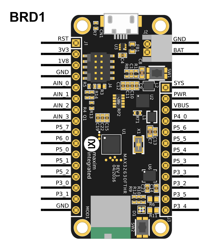
MAX32630FTHR Pegasus Board
The MAX32630FTHR Pegasus board is a rapid development platform designed to help engineers quickly implement battery optimized solutions with the MAX32630 ARM® Cortex® -M4F microcontroller. The board also includes the MAX14690 wearable PMIC to provide optimal power conversion and battery management.
-MAX32630 Microcontroller
Features:
ARM Cortex-M4F, 96MHz-2048KB Flash Memory
512KB SRAM
8KB Instruction Cache
Full-Speed USB 2.0
Three SPI Masters, One Slave
Three I2C Masters, One Slave
Four UARTS
1-Wire Master
66 GPIO
4 Input 10-Bit ADC
-MAX14690 Wearable PMIC
Battery Charger with Smart Selector
Dual Micro IQ Buck Regulators
Three Micro IQ Linear Regulators
Power-On/Off Sequencing Controller
Voltage Monitor Multiplexer
-Expansion Connections
Breadboard-Compatible Headers
Micro SD Card Connector
Battery Connector
Micro USB Connector
-Integrated Peripherals
RGB Indicator LED
6-Axis Accelerometer/Gyro
Dual-Mode Bluetooth Module
User Pushbutton
-mbed® HDK Debug Interface
Drag-and-Drop Programming
SWD Debugger
Virtual UART Console
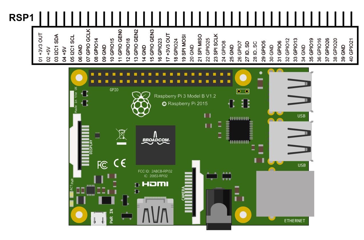
Raspberry Pi 3 Model B
The Raspberry Pi 3 is the third generation Raspberry Pi model. It replaces the Raspberry Pi 2 Model B. Compared to the Raspberry Pi 2 it has the following upgrades:
• A 1.2GHz 64-bit quad-core ARMv8 CPU
• 802.11n Wireless LAN
• Bluetooth 4.1
• Bluetooth Low Energy (BLE)
• 1GB RAM
• 4 USB ports
• 40 GPIO pins
• Full HDMI port
• Ethernet port
• Combined 3.5mm audio jack and composite video
• Camera interface (CSI)
• Display interface (DSI)
• Micro SD card slot (now push-pull rather than push-push)
• VideoCore IV 3D graphics core
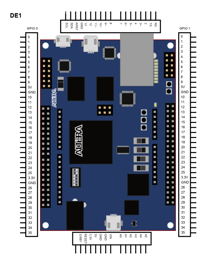
De0-Nano-SoC Development Kit
The DE0-Nano-SoC board is a hardware design platform based on the Altera System-on-Chip (SoC) FPGA, which combines the latest dual-core Cortex-A9 embedded cores with industry-leading programmable logic for ultimate design flexibility. It has many features that allow users to implement a wide range of designed circuits, from simple circuits to various multimedia projects.
FPGA Device
-Altera Cyclone® V SE 5CSEMA4U23C6N device
-Serial configuration device
-USB-Blaster II onboard for programming; JTAG mode
-2 push-buttons
-4 slide-switches
-8 green user LEDs
-Three 50MHz clock sources from the clock generator
-Two 40-pin expansion header
-One Arduino expansion header (Uno R3 compatibility), can connection with Arduino shields.
-One 10-pin analog input expansion header (shared with Arduino analog input).
-A/D converter, 4-pin SPI interface with FPGA
HPS (Hard Processor System)
-925MHz Dual-core ARM Cortex-A9 processor
-1GB DDR3 SDRAM (32-bit data bus)
-1 Gigabit Ethernet PHY with RJ45 connector
-USB OTG port, USB micro-AB connector
-Micro SD card socket
-Accelerometer (I2C interface plus interrupt)
-UART to USB, USB mini-B connector
-Warm-reset button and cold-reset button
-One user button and one user LED
-LTC 2 x 7 expansion header
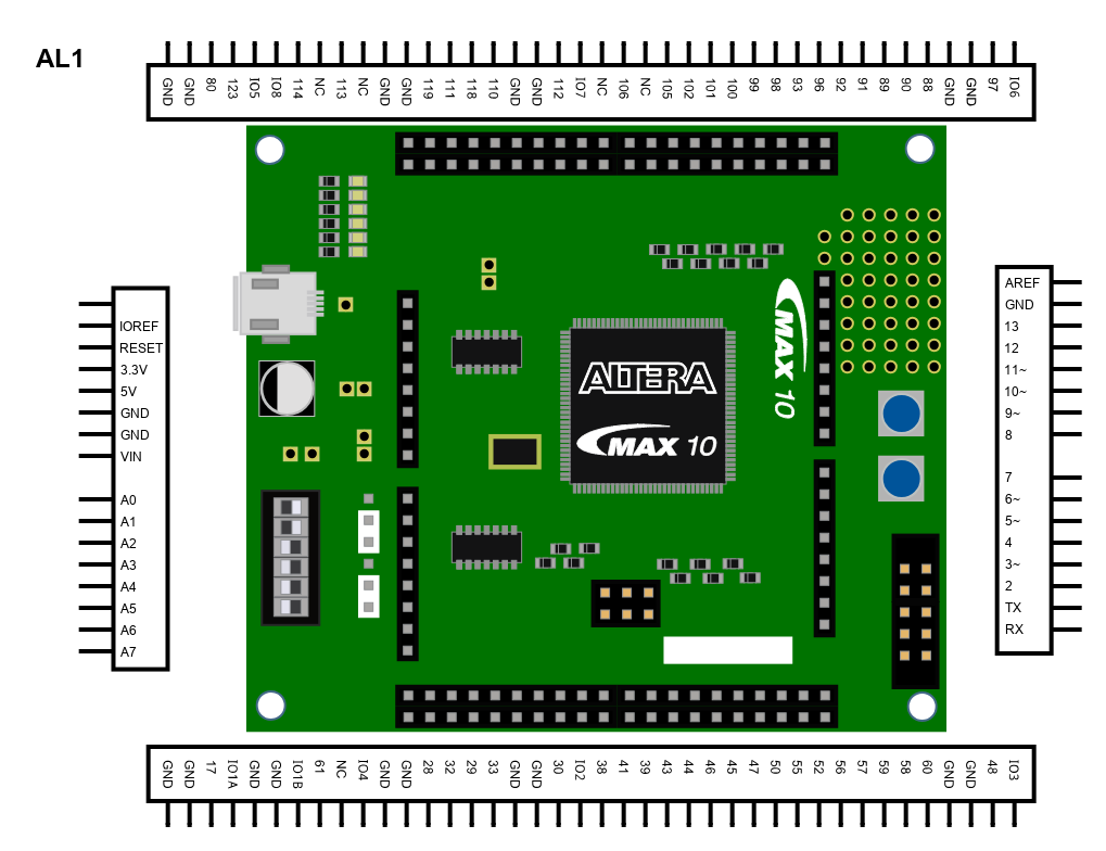
MAX 10 FPGA Evaluation Kit
The MAX 10 Evaluation Kit is an entry-level board for evaluating the MAX 10 FPGA technology and Enpirion PowerSoC regulators. This evaluation board features the following:
• MAX 10 FPGA (10M08, single power supply, 144-pin EQFP)
• Enpirion EP5388QI point-of-load PowerSoC, 800 mA, DC-DC step-down (buck) converter with an integrated inductor
• JTAG header for download cable programming (POF) or configuration (SOF)
• 50 MHz single-ended, external oscillator clock source
• Shunt resistors and probe points to measure FPGA power
• Switch, push buttons, jumpers, and status LEDs
This evaluation board also contains connectors such as the following:
• Arduino headers to accept UNO R3 compatible Shields
• General-purpose through-hole vias
• Type mini-B USB connector (power source)
• USB cable included
• Footprint to install a potentiometer (customer must purchase and install)
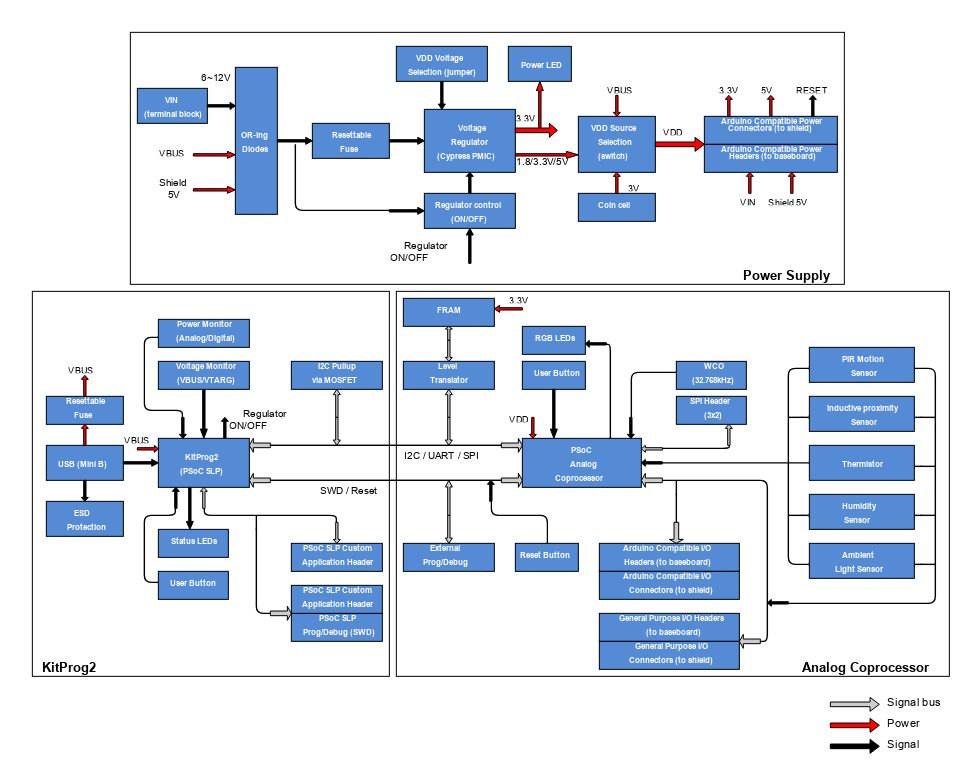
Analog Coprocessor
The PSoC Analog Coprocessor Pioneer Kit offers footprint-compatibility with Arduino™ shields and baseboards. This kit features five onboard sensors, an RGB LED, two push-button switches, an onboard programmer/debugger and USB-UART/I2C bridge functionality block (KitProg2), and a Cypress F-RAM™. This kit supports operating voltages of 1.8 V, 3.0 V (coin cell operated), 3.3 V or 5 V.
The Kit is intended for use with PSoC Creator™ to develop and debug your PSoC Analog Coprocessor device projects. PSoC Creator is Cypress' standard integrated design environment (IDE). If you are new to PSoC Creator, see the documentation on the PSoC Creator home page. You can also refer the application note, AN211293 – Getting Started with PSoC Analog Coprocessor, which gives an introduction to the PSoC Analog Coprocessor device.
For More information http://www.digikey.com/en/product-highlight/c/cypress/psoc-analog-coprocessor-with-te-sensor
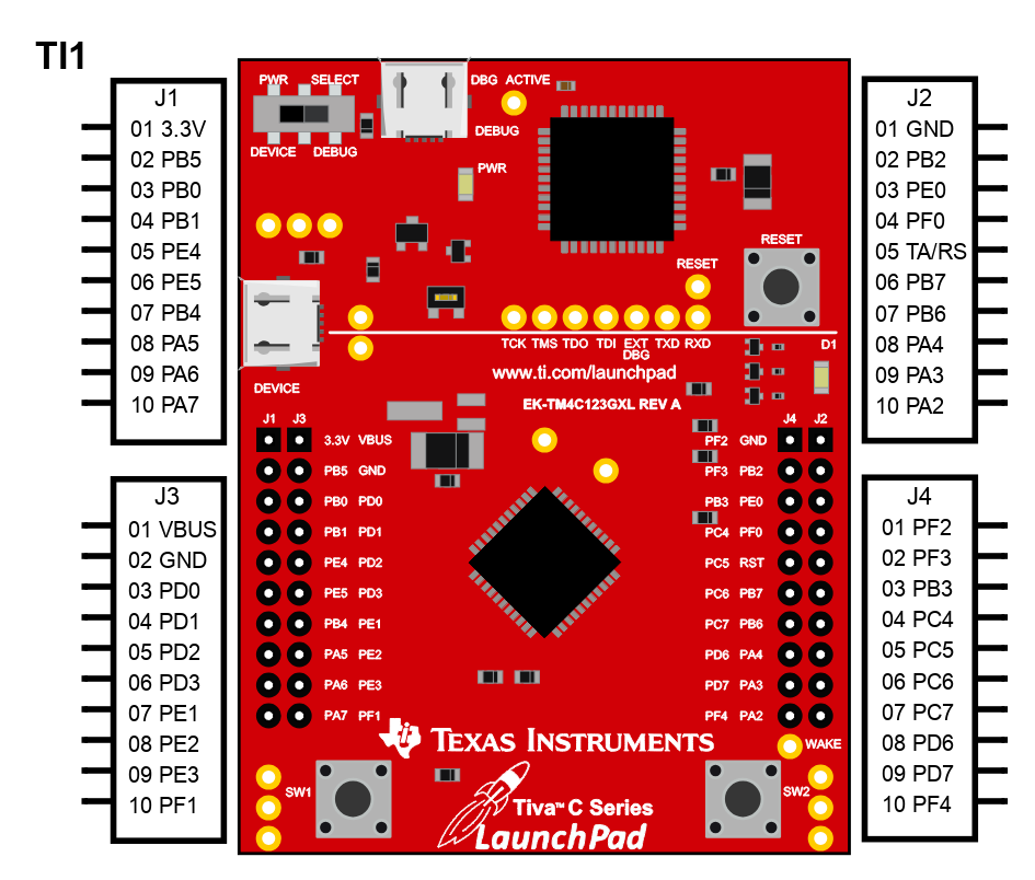
TM4C123G LaunchPad Evaluation Kit
The TM4C123G LaunchPad Evaluation Kit is a low-cost evaluation platform for ARM Cortex-M4F based microcontrollers from Texas Instruments. The EK-TM4C123GXL also features programmable user buttons and an RGB LED for custom applications. The stackable headers of the TM4C123G LaunchPad BoosterPack XL Interface make it easy and simple to expand the functionality of the TM4C123G LaunchPad when interfacing to other peripherals with Texas Instruments MCU BoosterPack. The design of the TM4C123G LaunchPad highlights the TM4C123GH6PM microcontroller with a USB 2.0 device interface and hibernation module.
The ARM Cortex-M4F Based MCU TM4C123G LaunchPad Evaluation Kit (EK-TM4C123GXL) offers these features:
• Tiva TM4C123GH6PMI microcontroller
• Motion control PWM
• USB micro-A and micro-B connector for USB device, host, and on-the-go (OTG) connectivity
• RGB user LED
• Two user switches (application/wake)
• Available I/O brought out to headers on a 0.1-in (2.54-mm) grid
• On-board ICDI
• Switch-selectable power sources: – ICDI – USB device
• Reset switch
• Preloaded RGB quickstart application
• Supported by TivaWare for C Series software including the USB library and the peripheral driver library
• Tiva C Series TM4C123G LaunchPad BoosterPack XL Interface, which features stackable headers to expand the capabilities of the Tiva C Series LaunchPad development platform
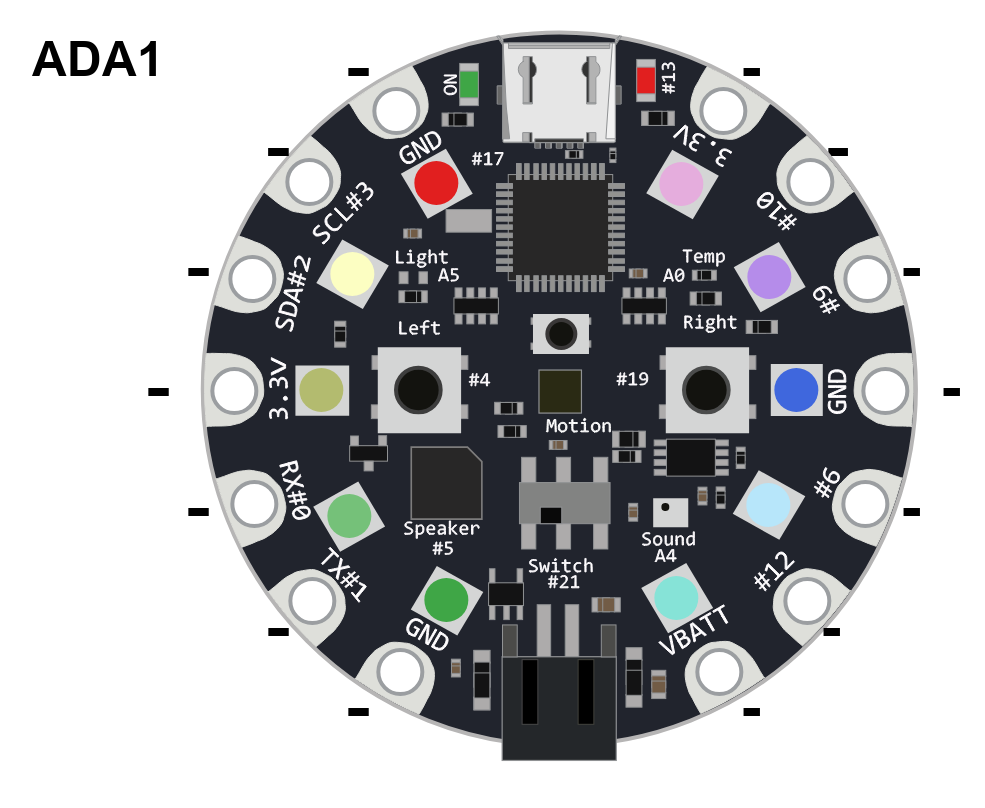
Circuit Playground 3000
Circuit Playground is an all-in-one board that has sensors and LEDs built in.
- ATmega32u4 Processor, running at 3.3V and 8MHz
- MicroUSB port for programming and debugging with Arduino IDE
- USB port can act like serial port, keyboard, mouse, joystick or MIDI
- 10 x mini NeoPixels, each one can display any color
- 1 x Motion sensor (LIS3DH triple-axis accelerometer with tap detection, free-fall detection)
- 1 x Temperature sensor (thermistor)
- 1 x Light sensor (phototransistor)
- 1 x Sound sensor (MEMS microphone)
- 1 x Mini speaker (magnetic buzzer)
- 2 x Push buttons, left and right
- 1 x Slide switch
- 8 x alligator-clip friendly input/output pins
- Includes I2C, UART, and 4 pins that can do analog inputs/PWM output
- All 8 pads can act as capacitive touch inputs
- Green "ON" LED so you know its powered
- Red "#13" LED for basic blinking
- Reset button
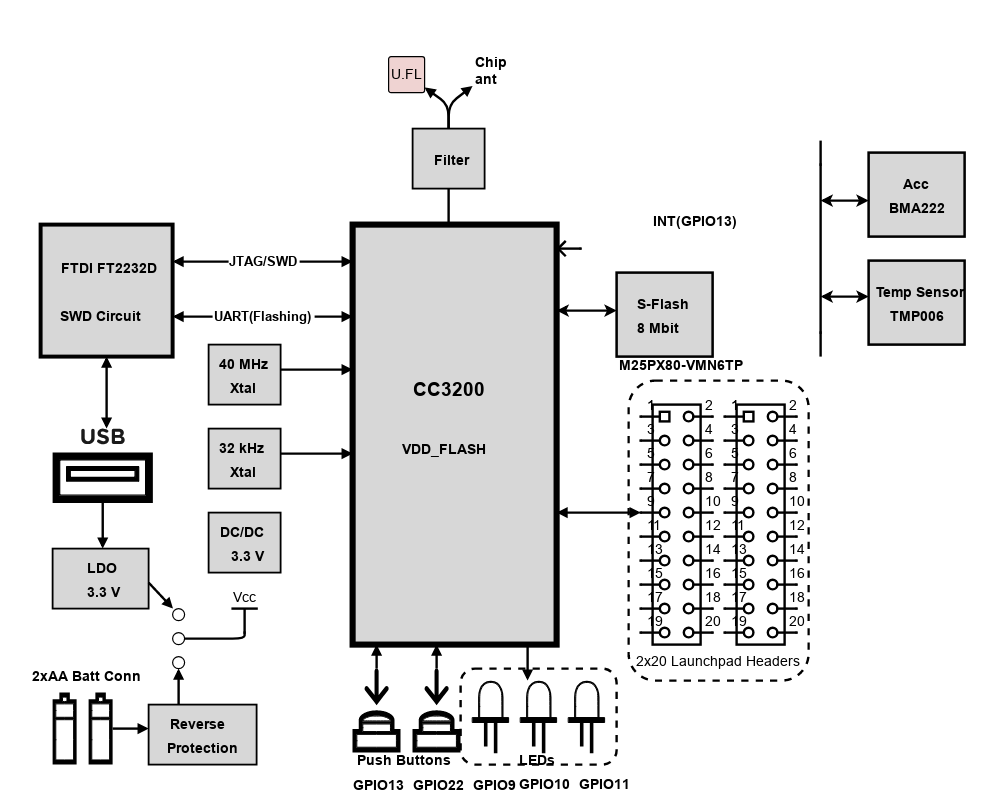
Scheme-it Block Diagram of CC3200 Launch Pad
CC3200 SimpleLink™ Wi-Fi® and IoT Solution with MCU LaunchPad Hardware.
The high performance CC3200 is the industry's first single-chip Microcontroller (MCU) with built-in Wi-Fi connectivity for the LaunchPad™ ecosystem. Created for the Internet of Things (IoT), the SimpleLink WiFi CC3200 device is a wireless MCU that integrates a high-performance ARM® Cortex®-M4 MCU allowing customers to develop an entire application with a single IC. With on-chip Wi-Fi, internet and robust security protocols, no prior Wi-Fi experience is needed for faster development.
Introduction
Schematic Drawings
Use schematic symbols to layout the components of your circuit and make electrical connections. With symbols ranging from amplifiers to vacuum tubes, as well as the ability to build custom symbols, you are able to design nearly any circuit. Access to Digi-Key's extensive part database also allows you to browse and assign orderable part numbers.
Diagram Building
Use the system blocks to refine your idea at a conceptual level. The higher-level components are there to help you plan out the broader intentions of your idea. This powerful block chain library allows you to quickly layout the function of circuit. Once your design is ready, save and share with your colleagues.
Flow Chart Creation
The flow chart creation option will help transition your concept to a design. Use the library of arrows, shapes, UML symbols, and more to sort out the flow and annotate each stage. Insert a textbox, math function/formula, image, or link to help illustrate the objectives and make your plan easy to follow.
Help & Resources
Need help? Ask questions in our TechForum

Conversion Calculators
Digi-Key's online conversion calculators offer a one-stop resource for many electronics industry calculations.
Go to Calculators
Conversion Calculators
Digi-Key's online conversion calculators offer a one-stop resource for many electronics industry calculations.
Go to Calculators

Reference Design Library
Search for designs based on the circuit's performance using Digi-Key's Reference Design Library.
Go to Reference Design Library
Reference Design Library
Search for designs based on the circuit's performance using Digi-Key's Reference Design Library.
Go to Reference Design Library
Tech Forum
Feedback
You are about to delete project
Please type 'DELETE' (without quotes) to the below box to confirm the deletion: