Scheme-it
Introduction
Schematic Drawings

Use schematic symbols to layout the components of your circuit and make electrical connections. With symbols ranging from amplifiers to vacuum tubes, as well as the ability to build custom symbols, you are able to design nearly any circuit. Access to Digi-Key's extensive part database also allows you to browse and assign orderable part numbers.
Diagram Building

Use the system blocks to refine your idea at a conceptual level. The higher-level components are there to help you plan out the broader intentions of your idea. This powerful block chain library allows you to quickly layout the function of circuit. Once your design is ready, save and share with your colleagues.
Flow Chart Creation

The flow chart creation option will help transition your concept to a design. Use the library of arrows, shapes, UML symbols, and more to sort out the flow and annotate each stage. Insert a textbox, math function/formula, image, or link to help illustrate the objectives and make your plan easy to follow.
Projects
Design Starters help give you a running start for your next design. Whether you are looking to begin a wireless charging platform or quickly design around a Bluetooth Low Energy module, our Design Starters will help get you quickly on your way.
Digi-Key has worked with industry leaders to help drive almost instantaneous ideation and these starters are ideal building blocks to help get your concepts created, drawn and documented in almost no time at all. Featured Design Starters
12 items
Refine Search
APPLICATION
MANUFACTURER
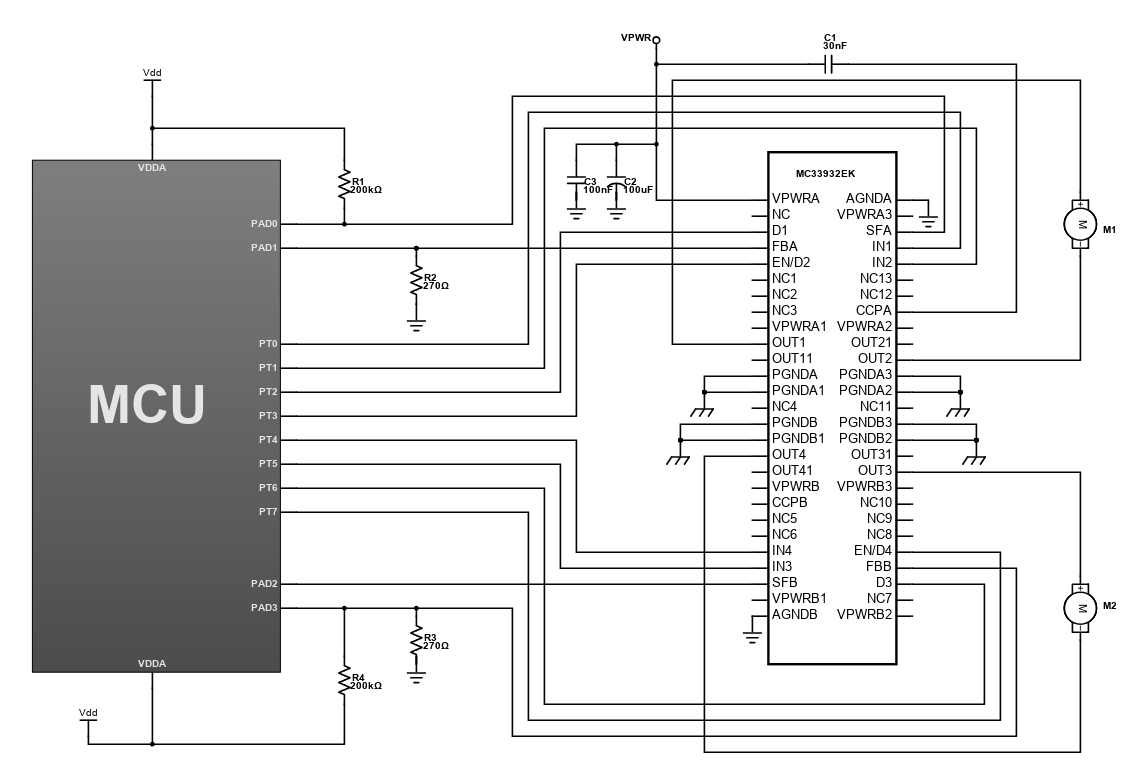
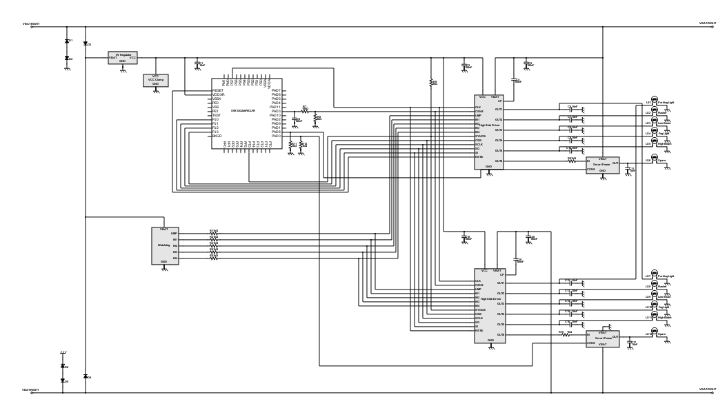
Basic Automotive Lighting Control with MCU
The electronics trend in automotive is continuously rising due to the demand in the market. The technological developments are now into embedded system in which the manufacturers are developing products that suits to the needs of the people. In this design, it features a automotive lighting control using an MCU with S12 CPU core, 25 MHz bus and up to 240 KB on-chip flash with Error Correction Code (ECC). The timer interface module (TIM) supports up to eight channels that provide a range of 16-bit input capture, output compare, counter and pulse accumulator functions. The on-chip SRAM is up to 12KB while 240KB for flash and 4KB for EEPROM.
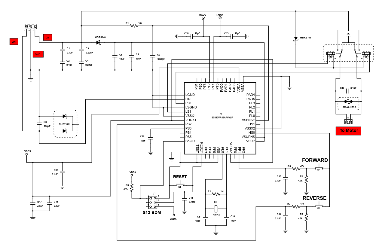
Controlling Relay Driven Motor using S9S12VR48AF0VLF
Interfacing a motor with a microcontroller gives us an easier way of controlling it. The programmability of a microcontroller makes it perfect for motor control applications. But one disadvantage of using a microcontroller for motor controls is that sometimes or most of the time, the high current passing through the coil of the motor is affecting the microcontroller's performance. Also, the blowback voltage generated by the motor when it's power supply is suddenly cut harms the microcontroller pin circuitry or sometimes blow up the entire microcontroller chip.
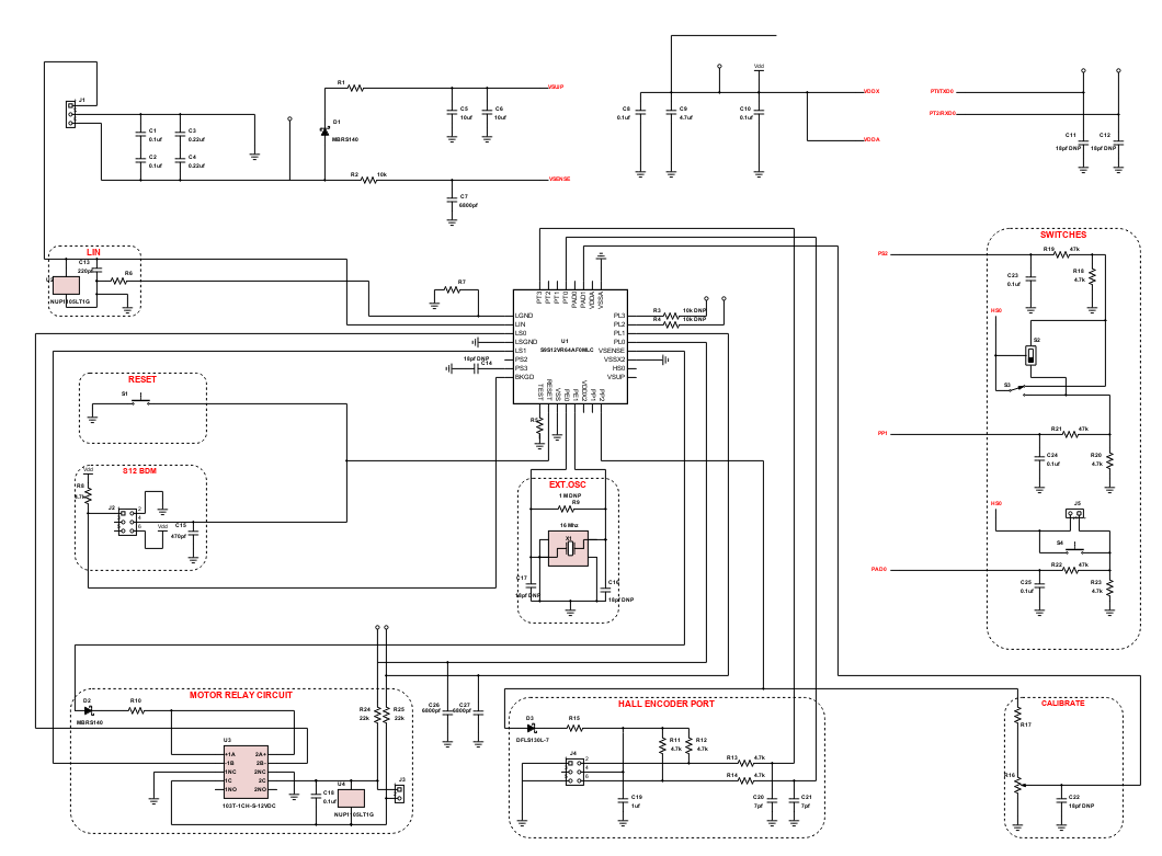
S12 MagniV Window Lift and Relay-based DC Motor Control
This is a reference design which features the S9S12VR64AF0MLC microcontroller (MCU), under the S12 MagniV MCU family from Freescale. In this design, advantages of the S12 MagniV 16-bit MCU are showcased for window lift and relay-based DC motor control applications. The circuit is simple with low amount of external components but has a high voltage capability.
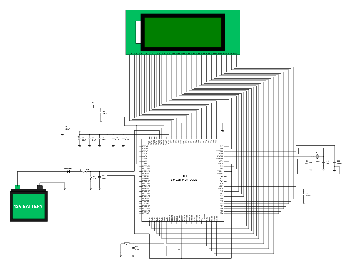
Car Battery Level Monitor
The battery plays a big role on the startup process of any car automotive system. It supplies the necessary current to start the engine. After starting the engine, the alternator begins to generate power and becomes the main source of electrical power to all electrical components within the car. When the current supplied by the alternator is not enough, the battery acts as an electrical reservoir and supplies the additional current required. Usually, failure in battery monitoring and maintenance causes problem to the start-up process of a car and in some other electrical components. That is why the goal of this reference design is to provide a simple circuit to display the battery level using a S912XHY128F0CLM microcontroller, a passive network sensor and an LCD display.
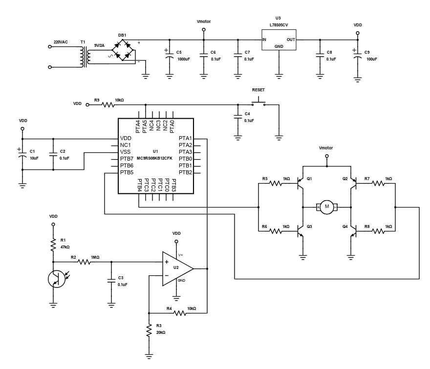
MC9RS08KB12CFK Window Blind Motor Controller
A window blind is a type of window covering that is used to manage the sunlight intensity, provide additional weatherproofing, ensure privacy and sometimes security, or used for purely decorative purposes. Some of the window blinds nowadays are automated and function according to how it was programmed by the user. In this reference design, the window blind opens or closes based on the intensity of light the circuit light sensor detects.
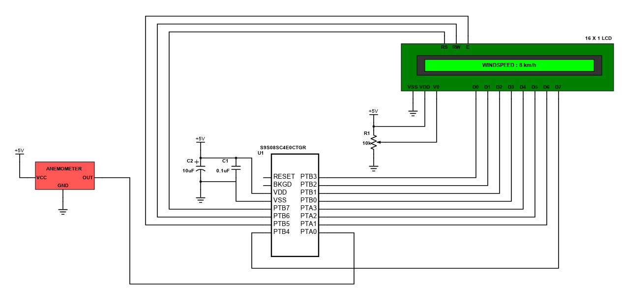
Interfacing an Anemometer with a S08 MCU
This project is a simple design of an anemometer interfaced with an S08 Microcontroller (MCU). An anemometer is a device that is used to measure wind speed. It is commonly used in weather stations. Anemometers are categorized as cup, vane, hot-wire, laser-Doppler, and sonic types. The anemometer used in this project is a cup type. This type of anemometer is usually has three or four cups on it to measure the wind speed.
HCS08 VGA Output
HCS08 VGA Output
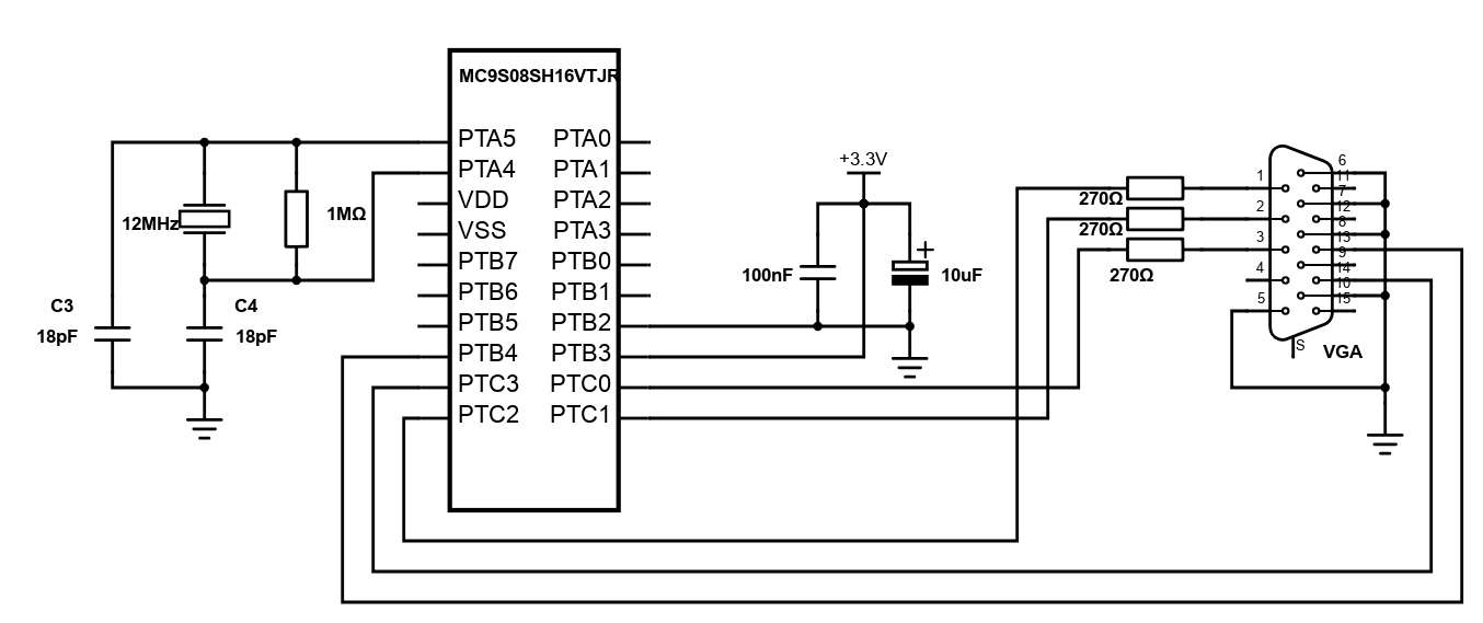
This reference design is a simple VGA signal generation that uses the Freescale's MC9S08SH16VTJR, which is an 8-bit microcontroller that has Central Processor Unit (CPU) speed of 40MHz with a maximum bus frequency of 20MHz. It has an internal clock source module containing a Frequency-Locked Loop (FLL) controlled by internal or external reference. Its precision trimming of internal reference allows 0.2% resolution and 2% deviation over temperature and voltage with 1.5% deviation using internal temperature compensation. The simplest instructions such as NOP take 1 bus cycle, the other instructions take more cycles, and for example RTS takes 6 bus cycles.
The VGA signal has 5 components that include horizontal synchronization, vertical synchronization and three analog color signals. The analog color signal range is 0-0.7V with 75Ω impedance and sync signals are TTL signals. The device has a refresh rate of 60Hz with 640 x 480 resolutions, and the pixel clock is 25.175MHz. The display refresh rate is therefore slightly lower, somewhere around 57Hz. The implementation for video signal generation is in the form of an infinite loop where one loop cycle is equal to one video frame. During every frame the video signal is generated line by line. A subroutine was created that draws multiple lines, where the number of lines is expected in the A register. Every line is divided into 16 parts. Colors of these parts are stored in RAM. Pointer to this array is expected in the HX register. Each of the 3 color channels is 1 bit only having 8 available basic colors.
The device is very simple that adds character to an ordinary static image displayed in an old CRT display. This can be easily reprogrammed as desired by the user. A scrolling strip may be added that is implemented as a rotating buffer. The circuit can be easily constructed using only an MCU, crystal oscillator, VGA connector and few capacitors.
Components
- MC9S08SH16VTJR MCU (U2)
- 270Ω Resistor (R1,R2,R3)
- 1MΩ Resistor (R4)
- 12MHz Crystal Oscillator (X1)
- VGA Connector (J2)
- 100nF Capacitor (C1)
10uF Capacitor (C2) - 18pF Capacitor (C3,C4)
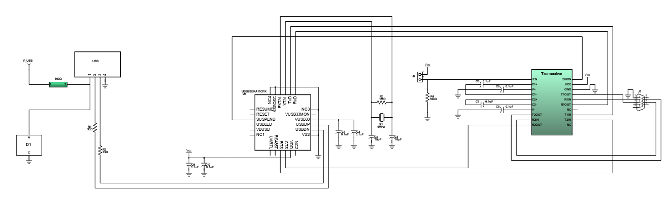
USB Interface to Microcontroller for Industrial
The reference design as shown is a RAppID boot loader tool connected to a TWR-PXR40 board. RAppID boot loader is a very useful tool in loading a new firmware to a microcontroller, and doing updates in its firmware without having access to the microcontroller's program or debug pins. It also contains a special module, which is called boot assist module (BAM) that can be used in order to download code to the microcontroller after it comes out of the factory.
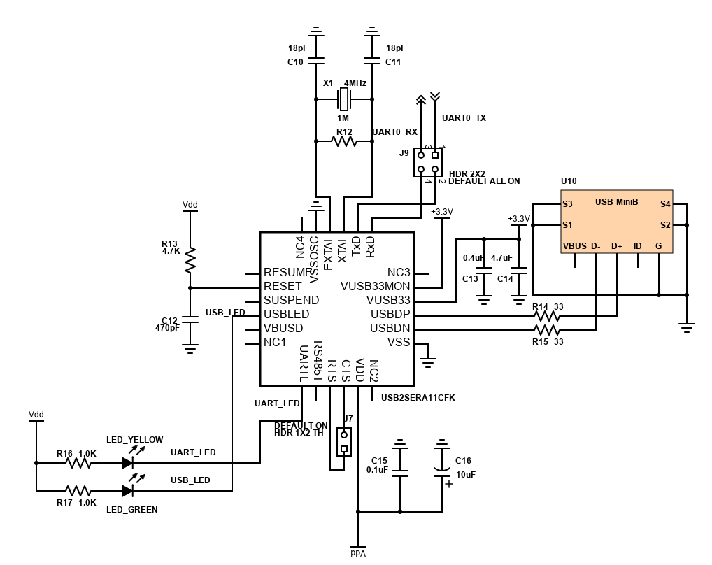
USB To UART Bridge Controller
This design features a USB to UART controller component. It enables the user to simplify designs by providing a UART port to a common USB embedded application. It features a USB 2.0 port with a data transfer speed of 12Mbps and a UART that supports 8 bit data, 1 or 2 stop bits and odd, even or no parity. The main component has built-in user configurable password that protects device from additional parameter modification.
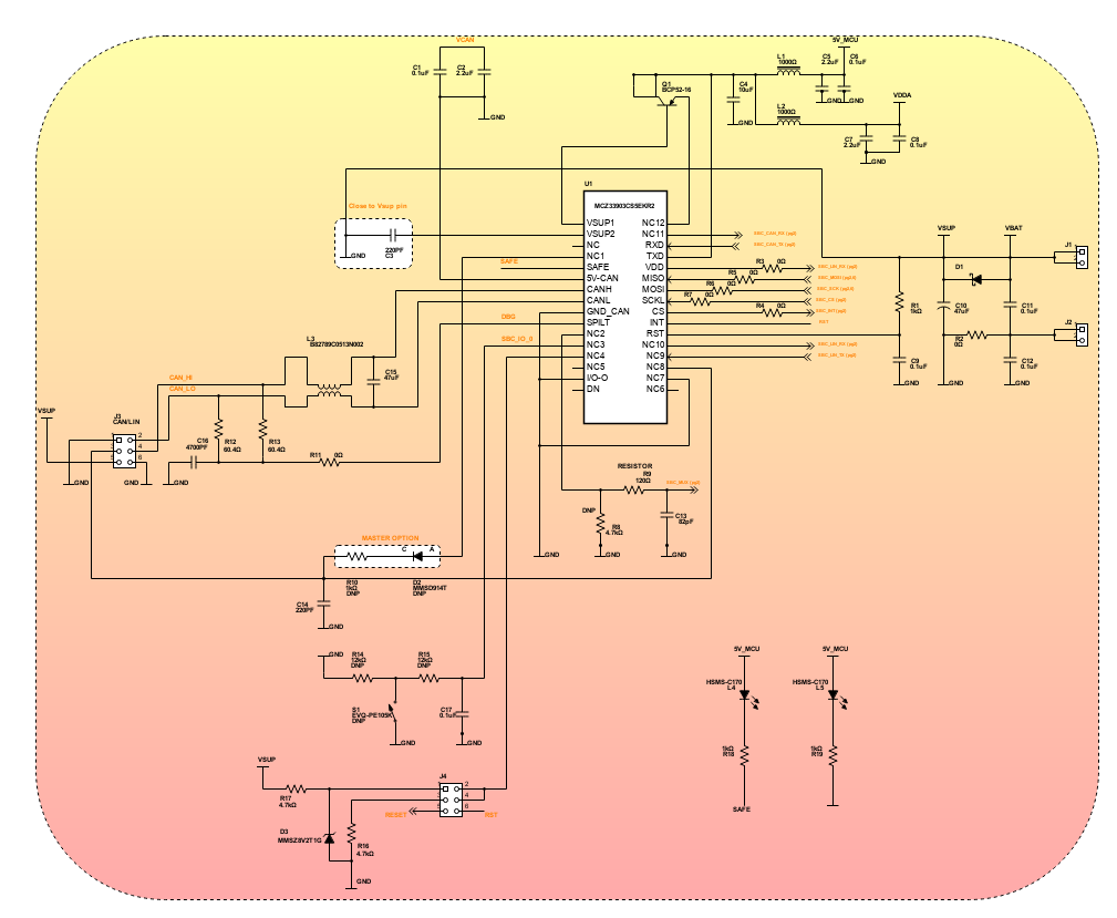
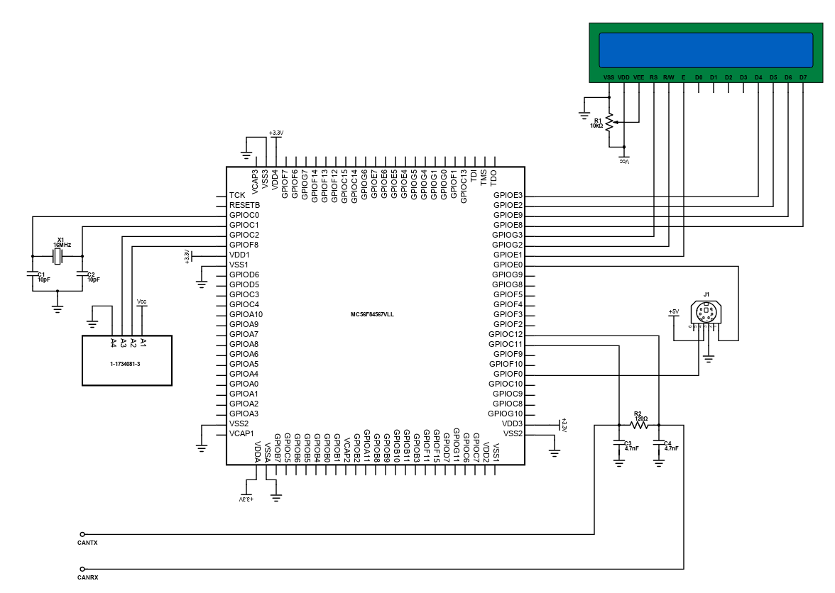
DSC Basic IO Management with CAN Interface
In the midst of automotive and industrial demand in the market, embedded electronic systems also increase in which the developments of some industries are now using this technology. This design features a system basis chip that can operate as LIN and CAN. It uses a DSC chip that combines the functionality of an MCU and a processing power of a DSP. It has 288KB on-chip memory and 32KB RAM and it can operate up to 80MHz program execution from both internal flash memory and RAM.
Introduction
Schematic Drawings
Use schematic symbols to layout the components of your circuit and make electrical connections. With symbols ranging from amplifiers to vacuum tubes, as well as the ability to build custom symbols, you are able to design nearly any circuit. Access to Digi-Key's extensive part database also allows you to browse and assign orderable part numbers.
Diagram Building
Use the system blocks to refine your idea at a conceptual level. The higher-level components are there to help you plan out the broader intentions of your idea. This powerful block chain library allows you to quickly layout the function of circuit. Once your design is ready, save and share with your colleagues.
Flow Chart Creation
The flow chart creation option will help transition your concept to a design. Use the library of arrows, shapes, UML symbols, and more to sort out the flow and annotate each stage. Insert a textbox, math function/formula, image, or link to help illustrate the objectives and make your plan easy to follow.
Help & Resources
Need help? Ask questions in our TechForum

Conversion Calculators
Digi-Key's online conversion calculators offer a one-stop resource for many electronics industry calculations.
Go to Calculators
Conversion Calculators
Digi-Key's online conversion calculators offer a one-stop resource for many electronics industry calculations.
Go to Calculators

Reference Design Library
Search for designs based on the circuit's performance using Digi-Key's Reference Design Library.
Go to Reference Design Library
Reference Design Library
Search for designs based on the circuit's performance using Digi-Key's Reference Design Library.
Go to Reference Design Library
Tech Forum
Feedback
You are about to delete project
Please type 'DELETE' (without quotes) to the below box to confirm the deletion: