Digi-key logo
scheme-it logo
Home
Design
BOM
Logout My Account
What’s New Digi-Key Tech Forum Keyboard Shortcuts Contact Us Page Help Page Feedback
Scheme-it settings
Auto save
Scheme-it
MAXREFDES99
MAXREFDES99

MAXREFDES99

MAXREFDES99# can be powered from a wall-wart which provides a minimum of 7W of power and an output voltage in the range of 7.5VDC to 12VDC. 7W is enough power for the display, plus the microcontroller platform being used through the VIN pin of the target platform. The reference design can be optionally powered from a USB port while developing application code, however, the user must take care not to exceed the power capabilities of the 5V rail supplied by their platform. The recommended method of powering MAXREFDES99# is through a wall-wart connected to J1.

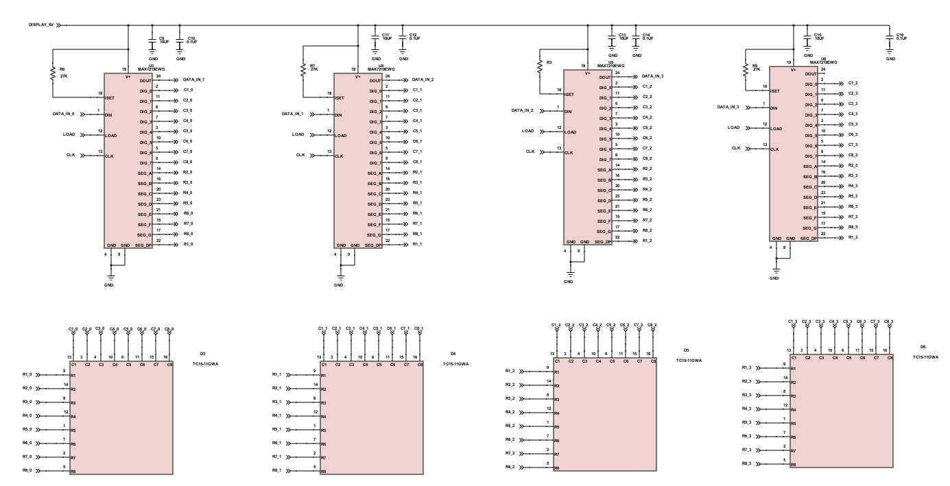
MAXREFDES99# uses the MAX3390E level translator to provide a 3.3V logic-level compatible interface to the four MAX7219 display drivers when using the shield with 3.3V platforms. The serial interface between the platform and the shield uses D10, D11, and D13 for LOAD, DIN, and CLK respectively. The four MAX7219 display drivers are daisy-chained connected with D11 connected to U3 and DOUT of U3 connected to DIN of U4 and so on. DOUT of U6 is left unconnected.

Read more
Open Design

Incorporated Products

IMAGE
MANUFACTURER PART NUMBER
DESCRIPTION
QUANTITY
VIEW DETAILS
1
MAX7219EWG
Rectangle
4
View Details
2
TC15-11GWA
Rectangle
4
View Details
3
PBC08SAAN
Rectangle
2
View Details
4
PBC06SAAN
Rectangle
1
View Details
5
PBC10SAAN
Rectangle
1
View Details
6
MAX17502FATB+
Rectangle
1
View Details
7
MAX3390EEUD+
Rectangle
1
View Details
8
12
PIN Left
12
View Details
9
8
PIN Right
12
View Details
10
21
PIN Right
12
View Details
11
6
PIN Right
12
View Details
12
4
PIN Left
3
View Details
13
2
PIN Bottom
3
View Details
14
3
PIN Bottom
3
View Details
15
10
PIN Top
12
View Details
16
1
PIN Left
3
View Details
17
C
PIN Bottom
3
View Details
18
PJ-002AH
Coax
1
View Details
19
PMEG2005EJ
VARIANT 1
1
View Details
20
PG1112H
VARIANT 1
1
View Details
21
EG2219
1
View Details
MAX7219EWG
Rectangle
Quantity: 4
View Details
TC15-11GWA
Rectangle
Quantity: 4
View Details
PBC08SAAN
Rectangle
Quantity: 2
View Details
PBC06SAAN
Rectangle
Quantity: 1
View Details
PBC10SAAN
Rectangle
Quantity: 1
View Details
MAX17502FATB+
Rectangle
Quantity: 1
View Details
MAX3390EEUD+
Rectangle
Quantity: 1
View Details
12
PIN Left
Quantity: 12
View Details
8
PIN Right
Quantity: 12
View Details
21
PIN Right
Quantity: 12
View Details
6
PIN Right
Quantity: 12
View Details
4
PIN Left
Quantity: 3
View Details
2
PIN Bottom
Quantity: 3
View Details
3
PIN Bottom
Quantity: 3
View Details
10
PIN Top
Quantity: 12
View Details
1
PIN Left
Quantity: 3
View Details
C
PIN Bottom
Quantity: 3
View Details
PJ-002AH
Coax
Quantity: 1
View Details
PMEG2005EJ
VARIANT 1
Quantity: 1
View Details
PG1112H
VARIANT 1
Quantity: 1
View Details
EG2219
Quantity: 1
View Details

About this Schematic

Created By
Curtis Johnson
Last Updated
2024-02-15 20:16
What’s New
You are about to delete project

Please type 'DELETE' (without quotes) to the below box to confirm the deletion:

  • Introduction
  • Tutorial Videos
  • Homepage
  • Revision
  • Symbol Editor
  • KiCad Export(beta)
  • Favorite symbols
  • Net
  • Save/Open/Delete Projects
  • Autosave and History
  • Placing Symbols
  • Wiring Symbols
  • Adding/Editing Text
  • Math box
  • Share and Export
  • BOM Manager
  • Digi-Key Catalog
  • FAQ
Title