Digi-key logo
scheme-it logo
Home
Design
BOM
Logout My Account
What’s New Digi-Key Tech Forum Keyboard Shortcuts Contact Us Page Help Page Feedback
Scheme-it settings
Auto save
Scheme-it
prod test 0910
prod test 0910

prod test 0910

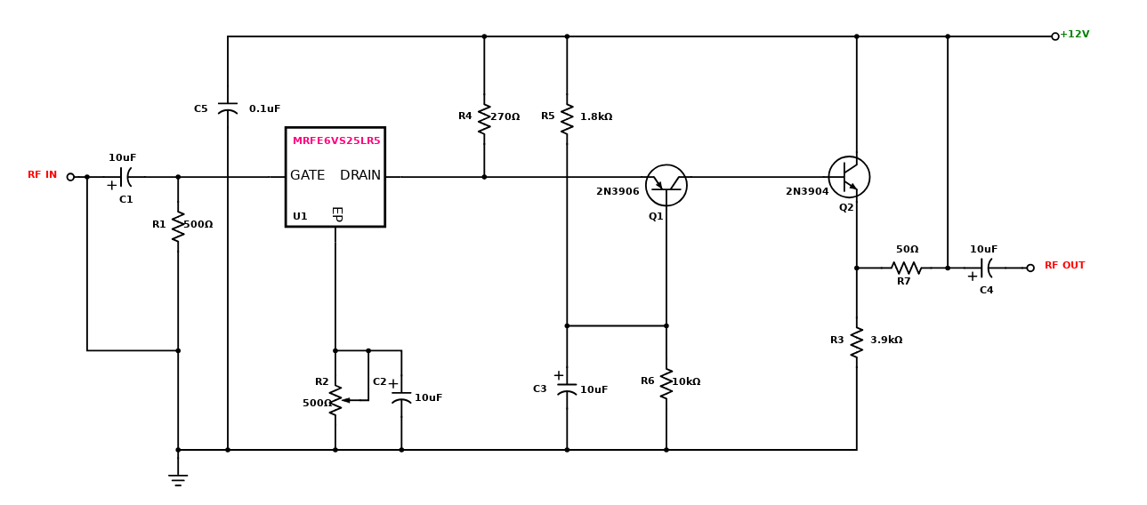
The circuit has a frequency response of up to 3 MHz with a gain that is about 30 dB. Field-effect transistor Ql is configured in the common-source self-biased mode; optional resistor R1 allows you to set the input impedance to any desired value. Commonly, it will be 50 . The signal is then direct-coupled to Q2, a common-base circuit that isolates the input and output stages and provides the amplifier`s exceptional stability. Last, Q3 functions as an emitter-follower, to provide low output impedance (about 50 ).If you need higher output impedance, include resistor R8. It will affect impedance according to this formula: Rs ~ ^0lJT - 50. Otherwise, connect output capacitor C4 directly to the emitter of Q3. This design is used in telecommunication system with frequency range of 1.8MHz to 2000MHz. Its basic applications include driving to another high power source, driving a transmitting antenna, microwave heating, and exciting resonant cavity structures. Among these applications, driving transmitter antennas is most well known. The transmitter–receivers are used not only for voice and data communication but also for weather sensing in the form of a RADAR.
Read more
Open Design

Incorporated Products

IMAGE
MANUFACTURER PART NUMBER
DESCRIPTION
QUANTITY
VIEW DETAILS
1
USA1C100MDD
4
View Details
2
Y1121500R000T9R
GENERAL
1
View Details
3
MRFE6VS25LR5
Wideband RF Power LDMOS Transistor, 1.8-2000 MHz, 25 W, 50 V
1
View Details
4
AVT02506E500R0KE
1
View Details
5
2N3906-AP
VARIANT 2
1
View Details
6
2N3904-AP
VARIANT 2
1
View Details
7
MCR03ERTF3901
GENERAL
1
View Details
8
ERJ-1TYJ271U
GENERAL
1
View Details
9
MCR01MRTF1801
GENERAL
1
View Details
10
MCR01MRTF1002
GENERAL
1
View Details
11
R2B131350R0J5L0
GENERAL
1
View Details
12
GRM155R71C104KA88D
VARIANT 2
1
View Details
USA1C100MDD
Quantity: 4
View Details
Y1121500R000T9R
GENERAL
Quantity: 1
View Details
MRFE6VS25LR5
Wideband RF Power LDMOS Transistor, 1.8-2000 MHz, 25 W, 50 V
Quantity: 1
View Details
AVT02506E500R0KE
Quantity: 1
View Details
2N3906-AP
VARIANT 2
Quantity: 1
View Details
2N3904-AP
VARIANT 2
Quantity: 1
View Details
MCR03ERTF3901
GENERAL
Quantity: 1
View Details
ERJ-1TYJ271U
GENERAL
Quantity: 1
View Details
MCR01MRTF1801
GENERAL
Quantity: 1
View Details
MCR01MRTF1002
GENERAL
Quantity: 1
View Details
R2B131350R0J5L0
GENERAL
Quantity: 1
View Details
GRM155R71C104KA88D
VARIANT 2
Quantity: 1
View Details

About this Schematic

Created By
vien pham
Last Updated
2020-02-13 02:16
What’s New
You are about to delete project

Please type 'DELETE' (without quotes) to the below box to confirm the deletion:

  • Introduction
  • Tutorial Videos
  • Homepage
  • Revision
  • Symbol Editor
  • KiCad Export(beta)
  • Favorite symbols
  • Net
  • Save/Open/Delete Projects
  • Autosave and History
  • Placing Symbols
  • Wiring Symbols
  • Adding/Editing Text
  • Math box
  • Share and Export
  • BOM Manager
  • Digi-Key Catalog
  • FAQ
Title