Scheme-it
Introduction
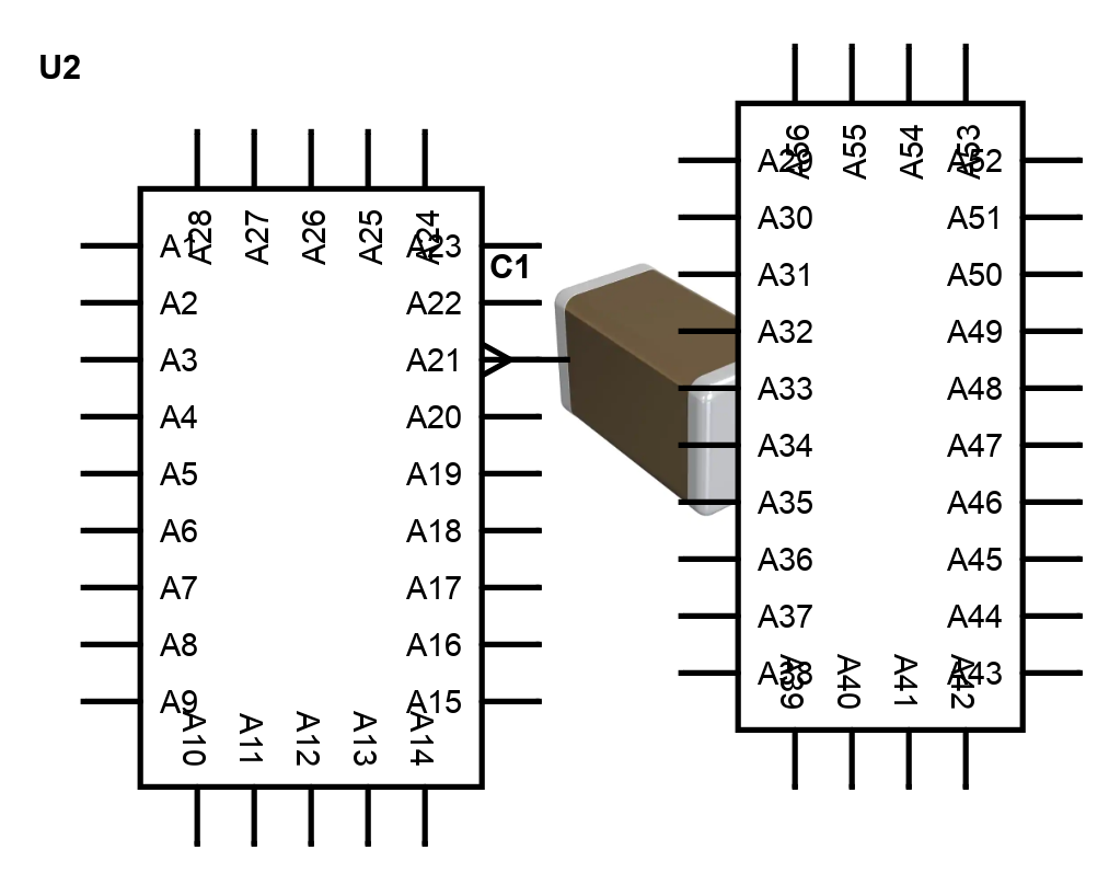
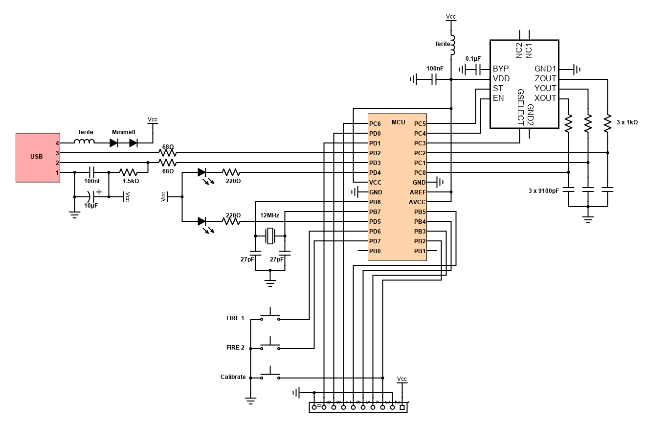
Schematic Drawings

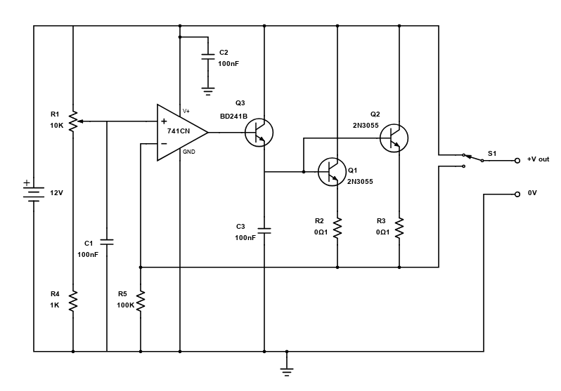
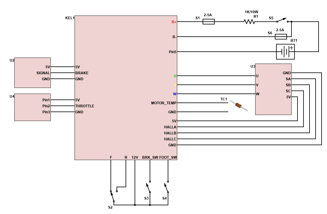
Use schematic symbols to layout the components of your circuit and make electrical connections. With symbols ranging from amplifiers to vacuum tubes, as well as the ability to build custom symbols, you are able to design nearly any circuit. Access to Digi-Key's extensive part database also allows you to browse and assign orderable part numbers.
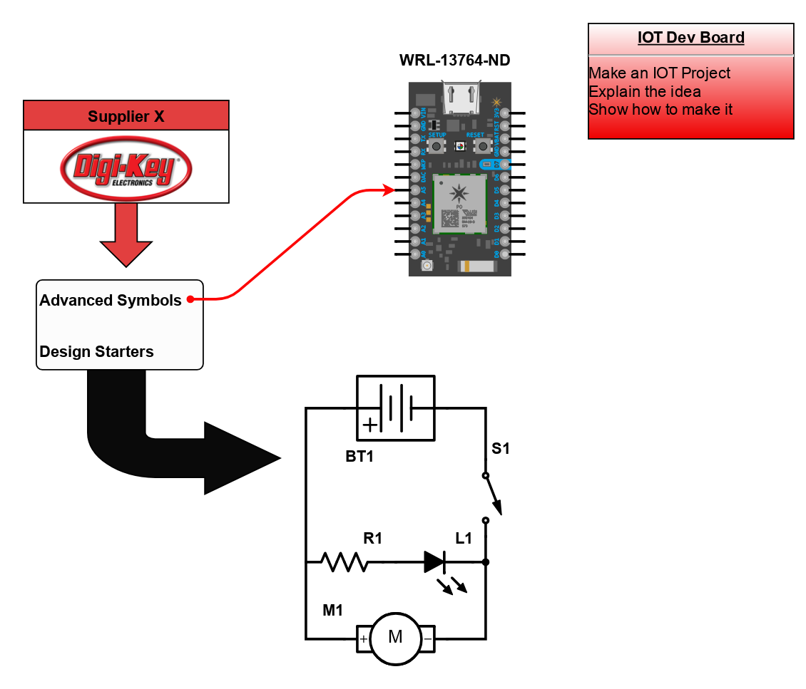
Diagram Building

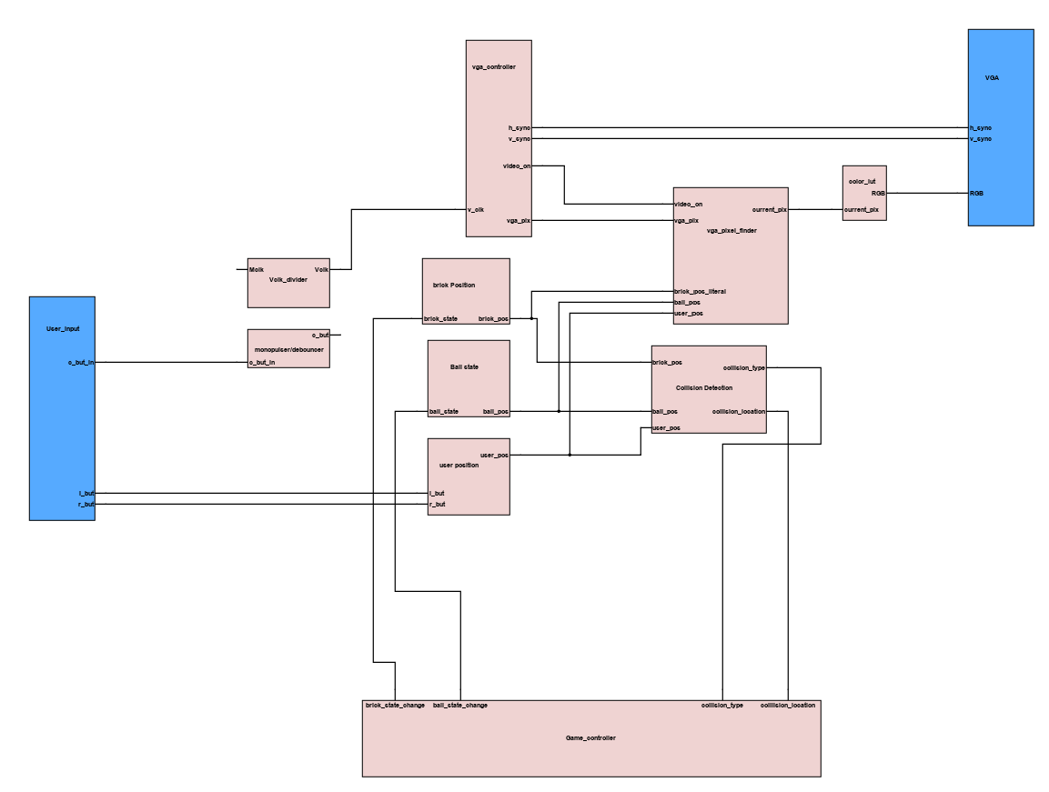
Use the system blocks to refine your idea at a conceptual level. The higher-level components are there to help you plan out the broader intentions of your idea. This powerful block chain library allows you to quickly layout the function of circuit. Once your design is ready, save and share with your colleagues.
Flow Chart Creation
The flow chart creation option will help transition your concept to a design. Use the library of arrows, shapes, UML symbols, and more to sort out the flow and annotate each stage. Insert a textbox, math function/formula, image, or link to help illustrate the objectives and make your plan easy to follow.
Projects
Refine Search
DATE RANGE
20200826_041112_0000 share a revision
2020-08-26 04:11:13
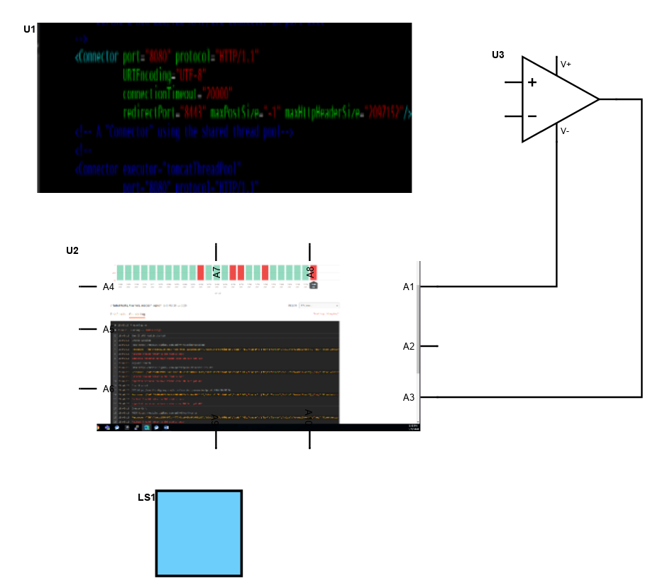
The self calibration mode has been added to allow for easy calibration without a special software tool running on the host; Press and hold the calibration button on the device for at least three seconds until the green LED turns off. The yellow calibration LED will then start blinking once a second to indicate that step one of the "self calibration" is in progress. Hold the device "flat" and press the calibration button again within 15 seconds. The yellow LED will start flashing twice each second to indicate that this was successful and that the second step of the calibration is to be performed. Tilt the device 90 degrees to the right and again press the calibration button within 15 seconds. The LED will start blinking three times each second. Tilt the device 90 degrees down and once more press the calibration button within 15 seconds. The LED will start blinking four times each second. Press the calibration button one last time within 15 seconds to permanently store the new calibration data inside the sticks internal EEPROM memory. The yellow LED will stop flashing and the green LED will turn on again. Calibration is done!
The accelerometers used on the device need to be calibrated in order to get accurate measurements in the range of -2G to +2G and to adjust the layout of the two axes to e.g. cope with the fact that the device may be oriented differently when attached to different host computers. The device can be used in conjunction with any software that can be controlled using a simple two axis joystick with two fire buttons, however, the device is not a joystick.
Introduction
Schematic Drawings
Use schematic symbols to layout the components of your circuit and make electrical connections. With symbols ranging from amplifiers to vacuum tubes, as well as the ability to build custom symbols, you are able to design nearly any circuit. Access to Digi-Key's extensive part database also allows you to browse and assign orderable part numbers.
Diagram Building
Use the system blocks to refine your idea at a conceptual level. The higher-level components are there to help you plan out the broader intentions of your idea. This powerful block chain library allows you to quickly layout the function of circuit. Once your design is ready, save and share with your colleagues.
Flow Chart Creation
The flow chart creation option will help transition your concept to a design. Use the library of arrows, shapes, UML symbols, and more to sort out the flow and annotate each stage. Insert a textbox, math function/formula, image, or link to help illustrate the objectives and make your plan easy to follow.
Help & Resources
Need help? Ask questions in our TechForum

Conversion Calculators
Digi-Key's online conversion calculators offer a one-stop resource for many electronics industry calculations.
Go to Calculators
Conversion Calculators
Digi-Key's online conversion calculators offer a one-stop resource for many electronics industry calculations.
Go to Calculators

Reference Design Library
Search for designs based on the circuit's performance using Digi-Key's Reference Design Library.
Go to Reference Design Library
Reference Design Library
Search for designs based on the circuit's performance using Digi-Key's Reference Design Library.
Go to Reference Design Library
Tech Forum
Feedback
You are about to delete project
Please type 'DELETE' (without quotes) to the below box to confirm the deletion: