Scheme-it
Introduction
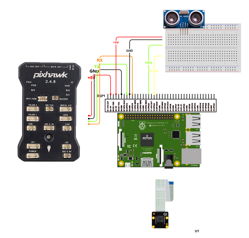
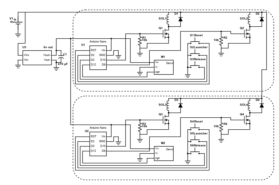
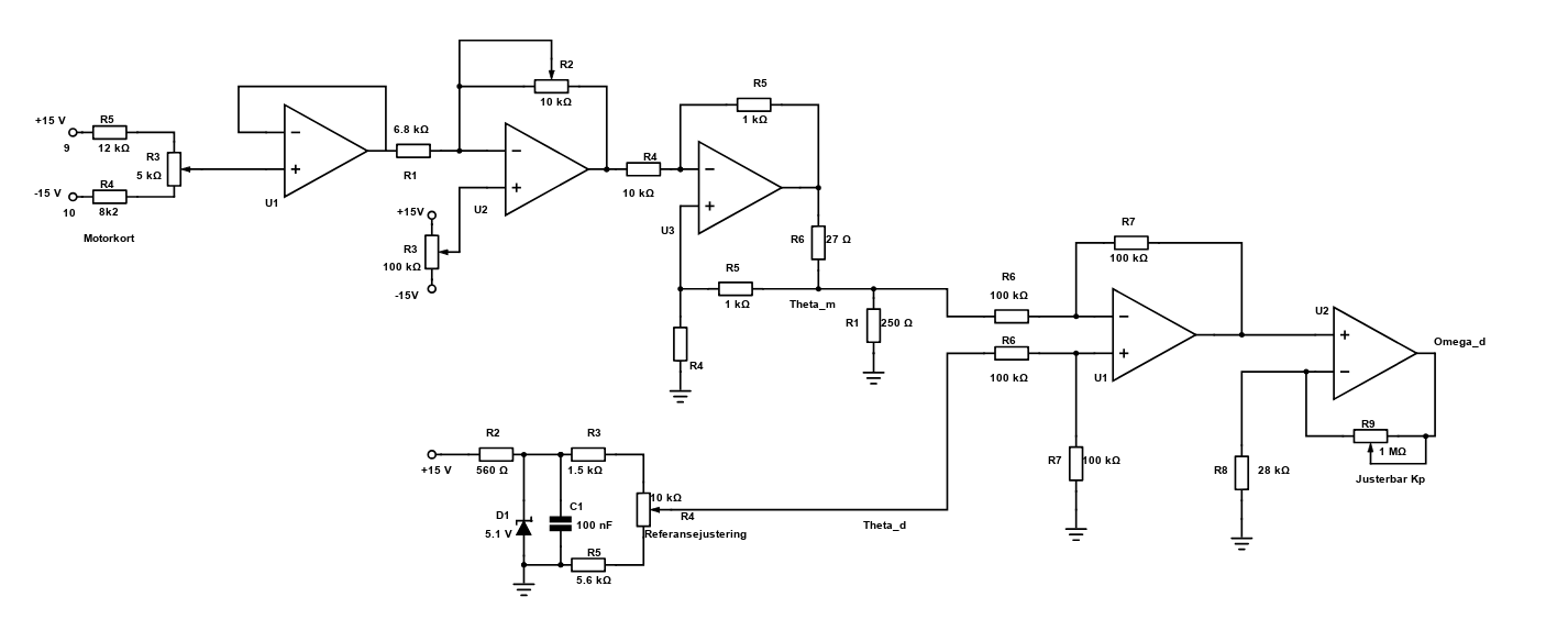
Schematic Drawings

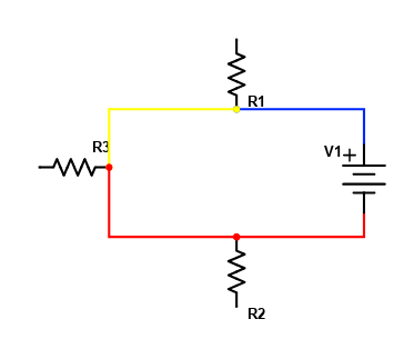
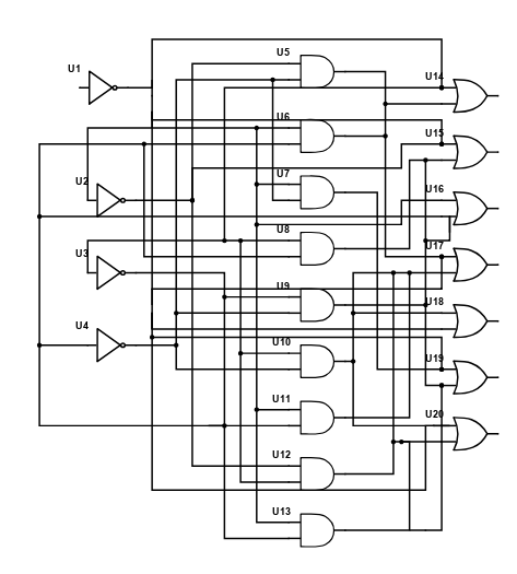
Use schematic symbols to layout the components of your circuit and make electrical connections. With symbols ranging from amplifiers to vacuum tubes, as well as the ability to build custom symbols, you are able to design nearly any circuit. Access to Digi-Key's extensive part database also allows you to browse and assign orderable part numbers.
Diagram Building

Use the system blocks to refine your idea at a conceptual level. The higher-level components are there to help you plan out the broader intentions of your idea. This powerful block chain library allows you to quickly layout the function of circuit. Once your design is ready, save and share with your colleagues.
Flow Chart Creation
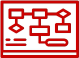
The flow chart creation option will help transition your concept to a design. Use the library of arrows, shapes, UML symbols, and more to sort out the flow and annotate each stage. Insert a textbox, math function/formula, image, or link to help illustrate the objectives and make your plan easy to follow.
Projects
Refine Search
DATE RANGE

5657677
2020-02-18 16:18:01
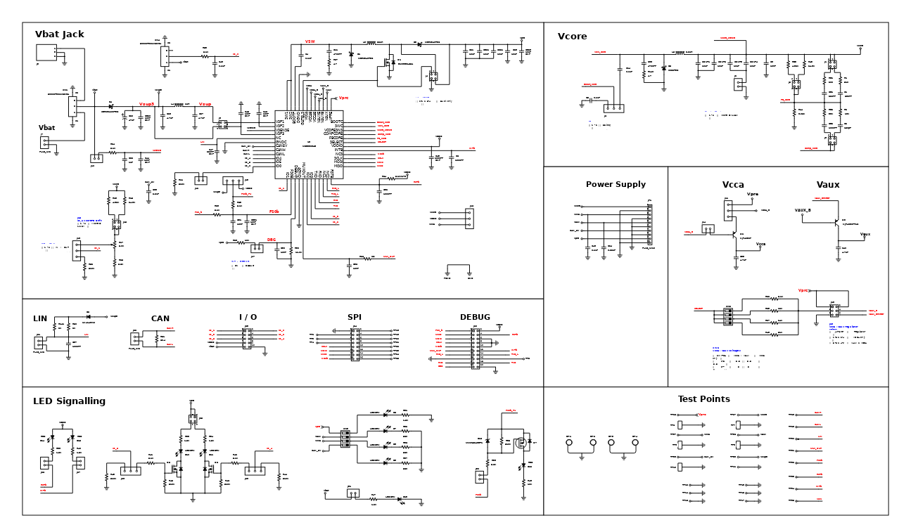
The KIT33907AEEVB and KIT33908AEEVB evaluation boards demonstrate the functionality of the SMARTMOS MC33907 and MC33908 power system basis chips, respectively. These ICs are equipped with an intelligent power management system including safety features targeting the latest ISO26262 automotive functional safety standard. The evaluation board is a standalone board that can be used either with a compatible microcontroller or with PC. In the latter case, it is necessary to use a KITUSBSPIDGLEVME accessory interface board. The MC33907 and the MC33908 are multi-output ICs with power supply and HSCAN transceiver. These devices have been designed specifically for automotive market. All features of thse two ICs are the same except that the MC33907 is designed to support up 800 mA on VCORE, while MC33908 will support up to 1.5A on VCORE. The DC to DC converter that supports up to 1.5A on VCORE has the following applications: electrical power steering, engine management, battery management, active suspension, gearbox, transmission, electrical vehicle (EV), hybrid electrical vehicle (HEV) and advanced driver assistance systems.
Introduction
Schematic Drawings
Use schematic symbols to layout the components of your circuit and make electrical connections. With symbols ranging from amplifiers to vacuum tubes, as well as the ability to build custom symbols, you are able to design nearly any circuit. Access to Digi-Key's extensive part database also allows you to browse and assign orderable part numbers.
Diagram Building
Use the system blocks to refine your idea at a conceptual level. The higher-level components are there to help you plan out the broader intentions of your idea. This powerful block chain library allows you to quickly layout the function of circuit. Once your design is ready, save and share with your colleagues.
Flow Chart Creation
The flow chart creation option will help transition your concept to a design. Use the library of arrows, shapes, UML symbols, and more to sort out the flow and annotate each stage. Insert a textbox, math function/formula, image, or link to help illustrate the objectives and make your plan easy to follow.
Help & Resources
Need help? Ask questions in our TechForum

Conversion Calculators
Digi-Key's online conversion calculators offer a one-stop resource for many electronics industry calculations.
Go to Calculators
Conversion Calculators
Digi-Key's online conversion calculators offer a one-stop resource for many electronics industry calculations.
Go to Calculators

Reference Design Library
Search for designs based on the circuit's performance using Digi-Key's Reference Design Library.
Go to Reference Design Library
Reference Design Library
Search for designs based on the circuit's performance using Digi-Key's Reference Design Library.
Go to Reference Design Library
Tech Forum
Feedback
You are about to delete project
Please type 'DELETE' (without quotes) to the below box to confirm the deletion: