Scheme-it
Introduction
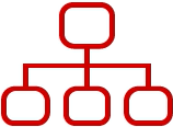
Schematic Drawings

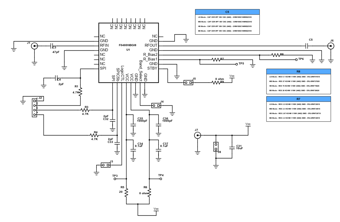
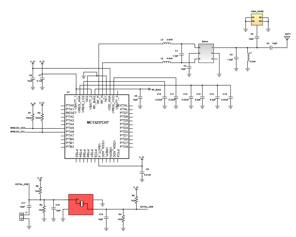
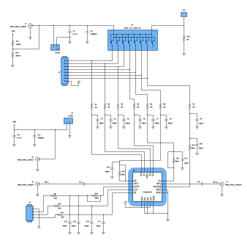
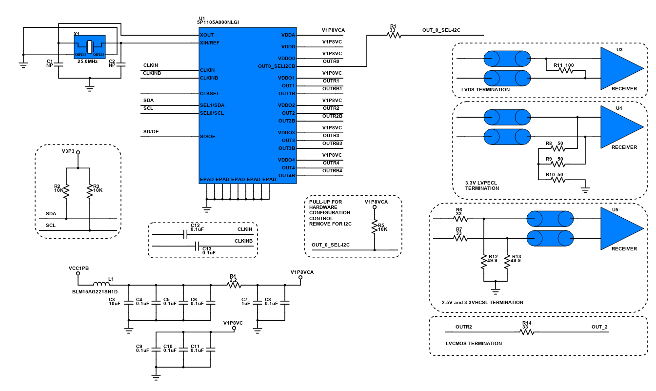
Use schematic symbols to layout the components of your circuit and make electrical connections. With symbols ranging from amplifiers to vacuum tubes, as well as the ability to build custom symbols, you are able to design nearly any circuit. Access to Digi-Key's extensive part database also allows you to browse and assign orderable part numbers.
Diagram Building
Use the system blocks to refine your idea at a conceptual level. The higher-level components are there to help you plan out the broader intentions of your idea. This powerful block chain library allows you to quickly layout the function of circuit. Once your design is ready, save and share with your colleagues.
Flow Chart Creation
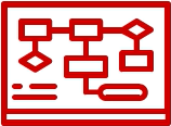
The flow chart creation option will help transition your concept to a design. Use the library of arrows, shapes, UML symbols, and more to sort out the flow and annotate each stage. Insert a textbox, math function/formula, image, or link to help illustrate the objectives and make your plan easy to follow.
Projects
Design Starters help give you a running start for your next design. Whether you are looking to begin a wireless charging platform or quickly design around a Bluetooth Low Energy module, our Design Starters will help get you quickly on your way.
Digi-Key has worked with industry leaders to help drive almost instantaneous ideation and these starters are ideal building blocks to help get your concepts created, drawn and documented in almost no time at all. Featured Design Starters
12 items
Refine Search
APPLICATION
MANUFACTURER
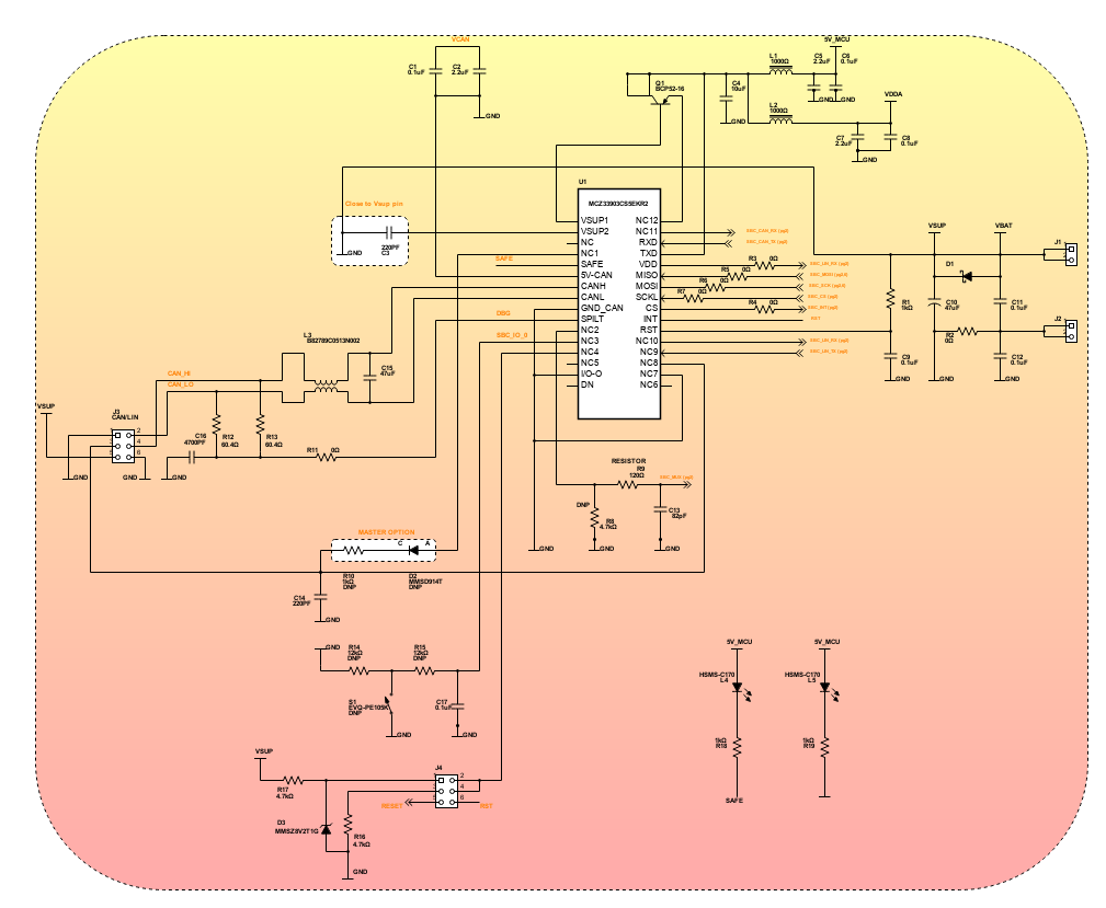
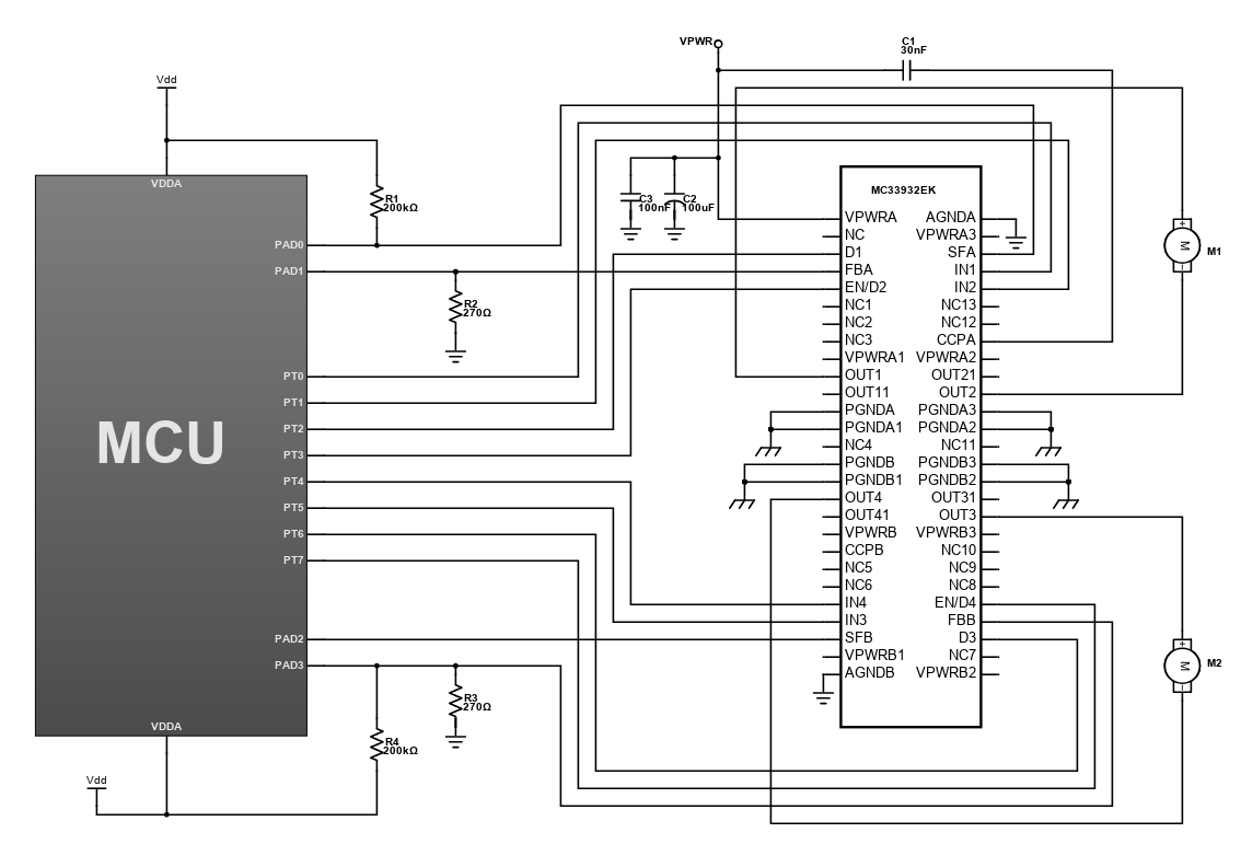
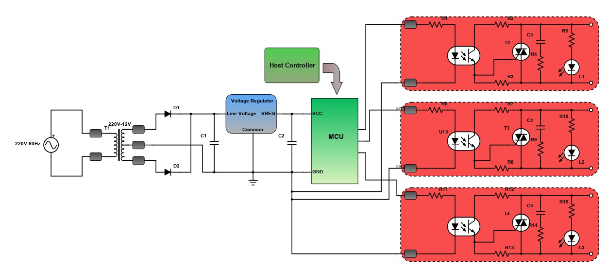
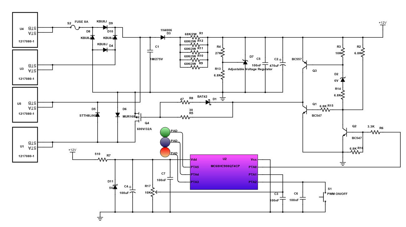
MCU-based Switching Control System
The schematic diagram as shown is a MCU-based switching control system. Nowadays, the basic tasks of turning ON or OFF certain devices and more can either be done remotely or in close proximity. Switching can now be done automatically from a central control point. Some advantages of this include convenience, sophistication and energy saving. Switching process can be done through a host controller. The channel may be wired like LAN or wireless like GSM and WLAN.
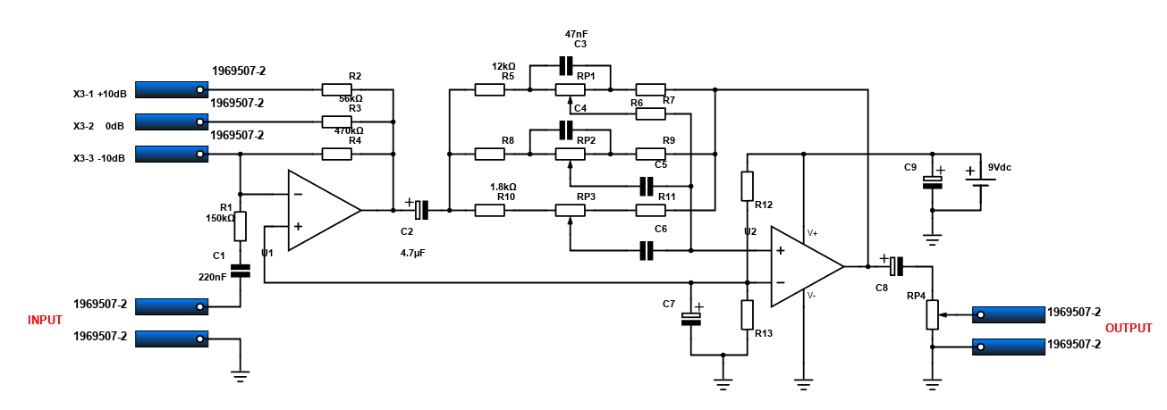
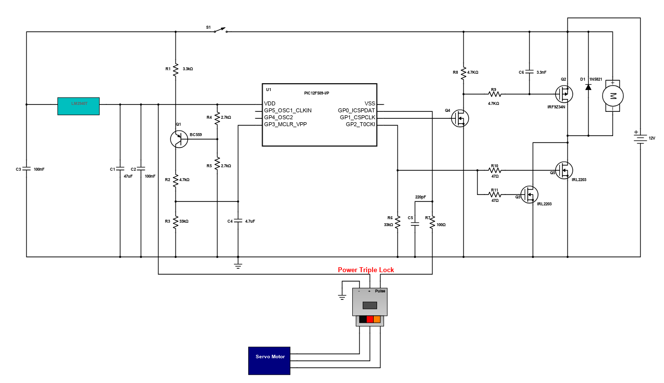
Electronic Speed Controller for RC Planes
An aerial control is nothing new to us in which there are several technologies that are being developed to optimize its capabilities. This radio controlled aircraft basically needs electronic speed controller to vary the electric motor's speed as well as its direction. It essentially provides an electronically generated electric power for the motor. This device can be a stand-alone unit which plugs into the receiver's throttle control channel or incorporated into the receiver itself. The device specially uses the TE Connectivity's Power Triple Lock System that ensures a strong connection between the ESC and the motor considering that RC plane needs good internal connection to avoid loss of communication during a flight.
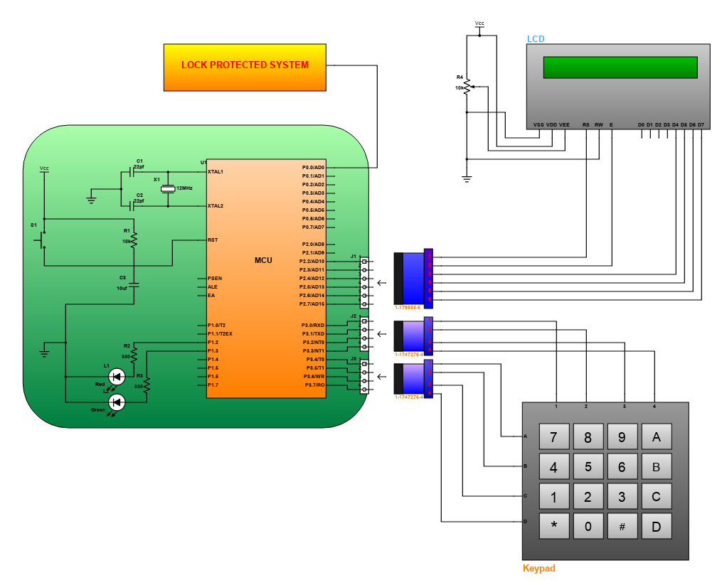
Password based Digital Locking System
This project is a password based digital locking system using a microcontroller. It is another type of security structure that asks users to enter a predefined password before allowing access to protected appliances, doors or other systems. The circuit utilizes the dynamic series connectors from TE connectivity to provide a reliable and strong connection in between components.
The design is primarily comprised of a microcontroller, an LCD interface, a matrix keypad and an electronic/electromechanical lock protected system. The dynamic series connectors provide connector solutions ranging from signal level circuitry up to power circuits. With the use of these connectors, disorganized wiring is avoided which makes circuit troubleshooting easy. In this password based digital locking system, the user is prompted to enter a password through the keypad, before allowing access. The entered password is sent to the microcontroller. Then, the microcontroller compares the entered password to the predefined password. If the passwords do not match, the red LED will glow and the LCD will display an error message. The user is required to press the reset button to enter a password again. If the passwords do match, the green LED will glow and the LCD will display a message "Successful Access". The microcontroller will then send a logic signal to unlock the protected system.
The design is very useful disallowing unauthorized persons gain access to the users' equipment. The design is applicable, but not limited to doors, gates, turnstiles, cabinets and moneyboxes.
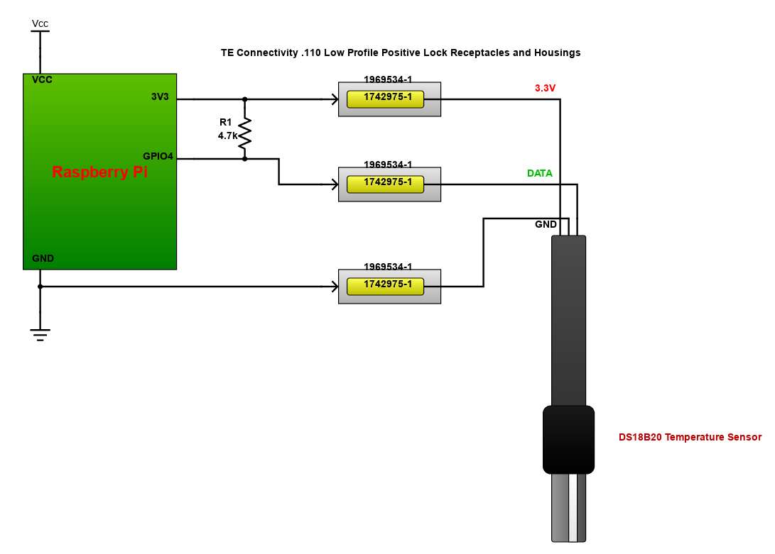
Digital Temperature Sensing Circuit
Temperature sensing equipment is a very useful device for industries like HVAC, medical equipment, automotive, food processing, chemical handling and safety applications. Temperature sensors are used to measure heat in processes to ensure that the operation is in a safe range.
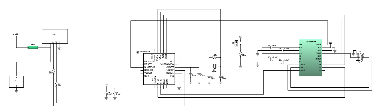
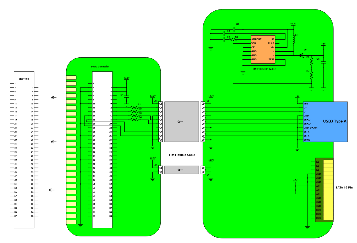
M.2 NGFF to USB3.0 Extend Board
The M.2 NGFF to USB3.0 Extend Board is designed with TE Connectivity's 2199119-8 socket, which allows USB 3.0 device to type 2242 Key B M.2 type slot in the Desktop or Laptop. It supports type 2230 M.2 Card dimension and M.2 key B card type. The standard 15-pin SATA external power requires a 5V supply. This project is designed both single and double-sided modules having a 0.5mm pitch width with 67 positions.
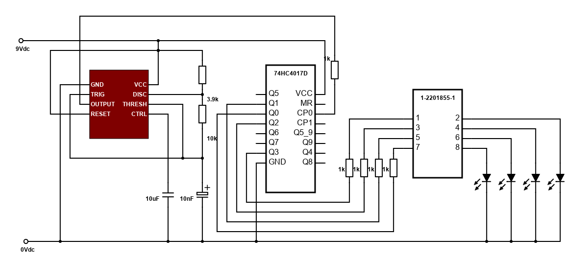
Open Loop Universal Motor Reference Design Chopper Based on the MC68HC908QT4 Manual Microcontroller
This reference design features a real-time application that can be very useful in different low-cost products. With the use of microcontroller, it allows the system to be programmable in the means of changing the defined constants within its software application. Using microcontroller has other advantages such as changing the control algorithm and by doing some re-programming; the microcontroller can be changed into a new firmware. The unused memory and capacity can still be of use in the next application purposes. Compared to some drivers like phase angle drive, a chopper driver requires a more complicated power stage, input rectifier usage, a power switch, and a fast high-powered diode.
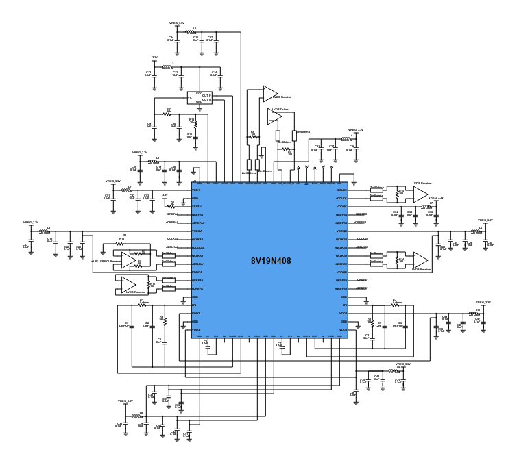
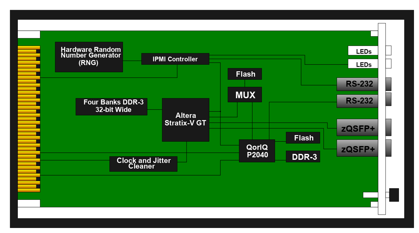
FPGA with Dual zQSFP+ Connectors Modem
Telecommunications, data center and networking markets require a high-speed, high-density connector. Today, connectors incorporate thermal management component (TMC) in a connector module that basically provides heat sinking and dissipation functions. TE Connectivity's 1551892-1 z-Quad Small Form-factor Pluggable Plus (zQSFP+) Interconnect System combines excellent signal integrity, electromagnetic interference protection and thermal cooling.
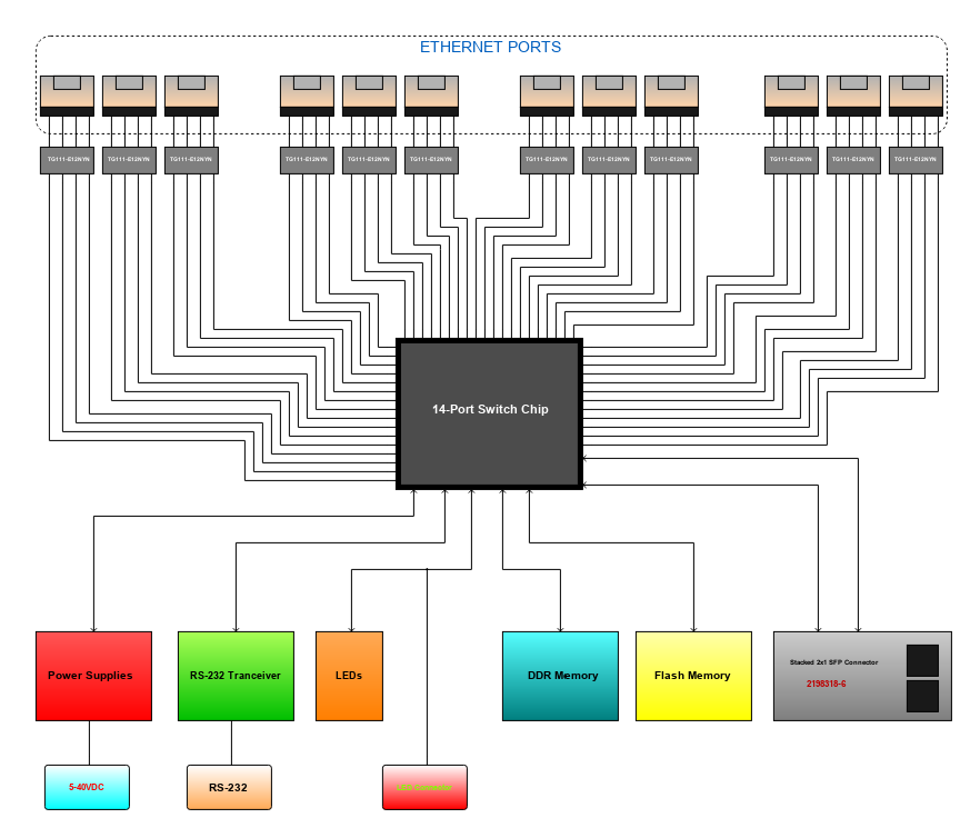
14-Port Gigabit Managed Ethernet Switch With 2 SFP Sockets
In interconnection networks, the ethernet switch or network switch is used to connect computers, printers and other network devices within an establishment. Its function is to control and enable network devices to communicate with each other efficiently. Network switches are mainly categorized as an unmanaged type or a managed type switch. Unmanaged type switches, are switches that do not need configuration for its installation, while managed type switches require configuration to be set up and be installed for its function. With this, the managed type switch offers greater flexibility and capacity than the unmanaged type switch. You can monitor and adjust a managed switch locally or remotely, which gives you greater network control.
Mini I/O Network Cable Tester
A cable tester is a gadget that utilizes the use of a compact size mini I/O connector of TE connectivity that features two points of contact interface with latching feature. This device is used to test the quality and network of a specific type of cable. There are various distinctive sorts of cable testers, each able to test a specific type of cable or wire.
Introduction
Schematic Drawings
Use schematic symbols to layout the components of your circuit and make electrical connections. With symbols ranging from amplifiers to vacuum tubes, as well as the ability to build custom symbols, you are able to design nearly any circuit. Access to Digi-Key's extensive part database also allows you to browse and assign orderable part numbers.
Diagram Building
Use the system blocks to refine your idea at a conceptual level. The higher-level components are there to help you plan out the broader intentions of your idea. This powerful block chain library allows you to quickly layout the function of circuit. Once your design is ready, save and share with your colleagues.
Flow Chart Creation
The flow chart creation option will help transition your concept to a design. Use the library of arrows, shapes, UML symbols, and more to sort out the flow and annotate each stage. Insert a textbox, math function/formula, image, or link to help illustrate the objectives and make your plan easy to follow.
Help & Resources
Need help? Ask questions in our TechForum

Conversion Calculators
Digi-Key's online conversion calculators offer a one-stop resource for many electronics industry calculations.
Go to Calculators
Conversion Calculators
Digi-Key's online conversion calculators offer a one-stop resource for many electronics industry calculations.
Go to Calculators

Reference Design Library
Search for designs based on the circuit's performance using Digi-Key's Reference Design Library.
Go to Reference Design Library
Reference Design Library
Search for designs based on the circuit's performance using Digi-Key's Reference Design Library.
Go to Reference Design Library
Tech Forum
Feedback
You are about to delete project
Please type 'DELETE' (without quotes) to the below box to confirm the deletion: