Scheme-it
Introduction
Schematic Drawings

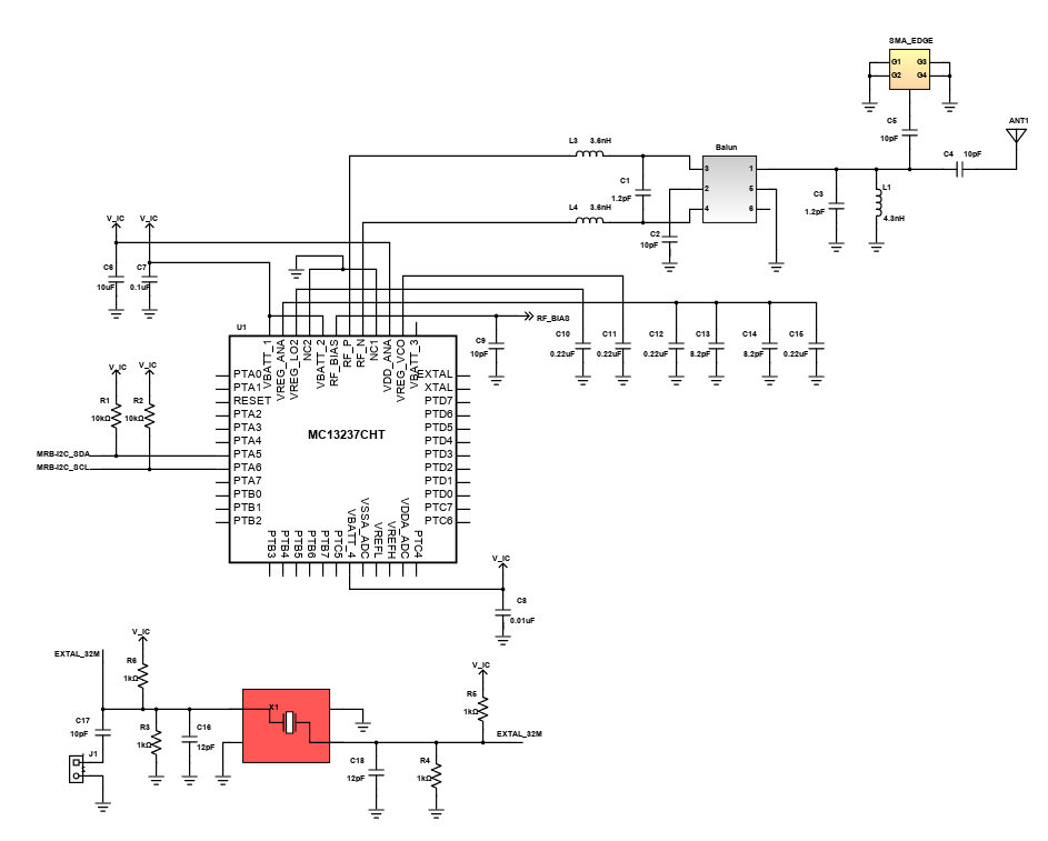
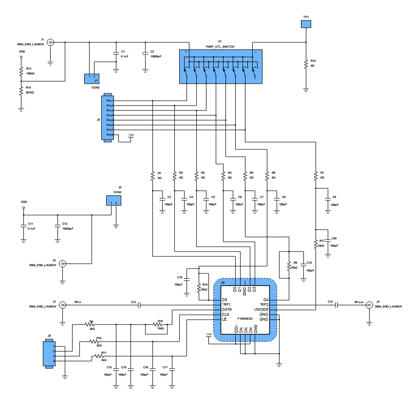
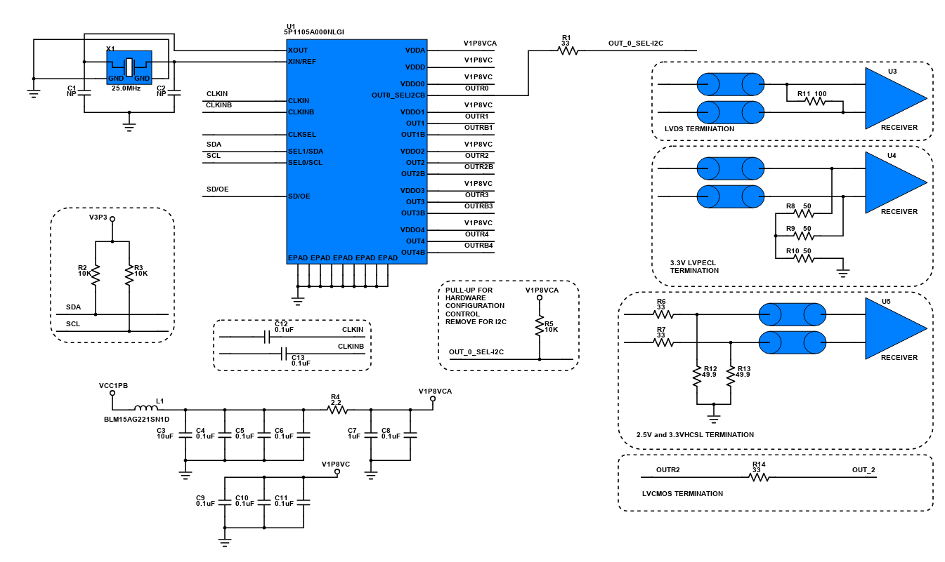
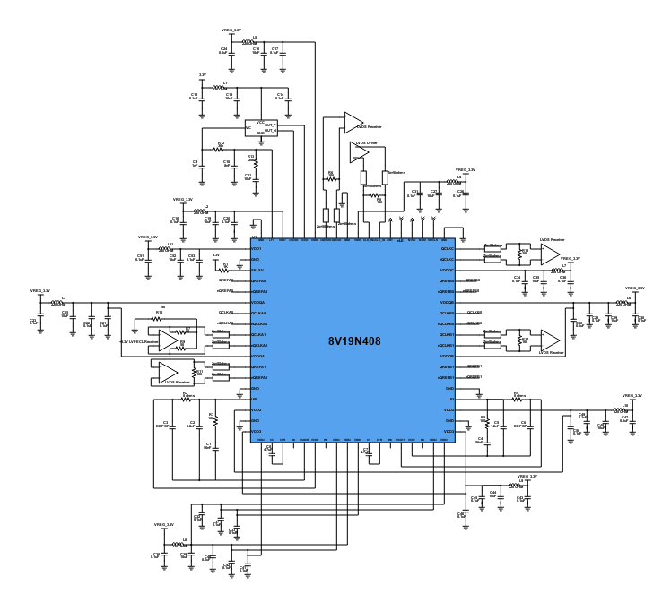
Use schematic symbols to layout the components of your circuit and make electrical connections. With symbols ranging from amplifiers to vacuum tubes, as well as the ability to build custom symbols, you are able to design nearly any circuit. Access to Digi-Key's extensive part database also allows you to browse and assign orderable part numbers.
Diagram Building

Use the system blocks to refine your idea at a conceptual level. The higher-level components are there to help you plan out the broader intentions of your idea. This powerful block chain library allows you to quickly layout the function of circuit. Once your design is ready, save and share with your colleagues.
Flow Chart Creation
The flow chart creation option will help transition your concept to a design. Use the library of arrows, shapes, UML symbols, and more to sort out the flow and annotate each stage. Insert a textbox, math function/formula, image, or link to help illustrate the objectives and make your plan easy to follow.
Projects
Design Starters help give you a running start for your next design. Whether you are looking to begin a wireless charging platform or quickly design around a Bluetooth Low Energy module, our Design Starters will help get you quickly on your way.
Digi-Key has worked with industry leaders to help drive almost instantaneous ideation and these starters are ideal building blocks to help get your concepts created, drawn and documented in almost no time at all. Featured Design Starters
12 items
Refine Search
APPLICATION
MANUFACTURER
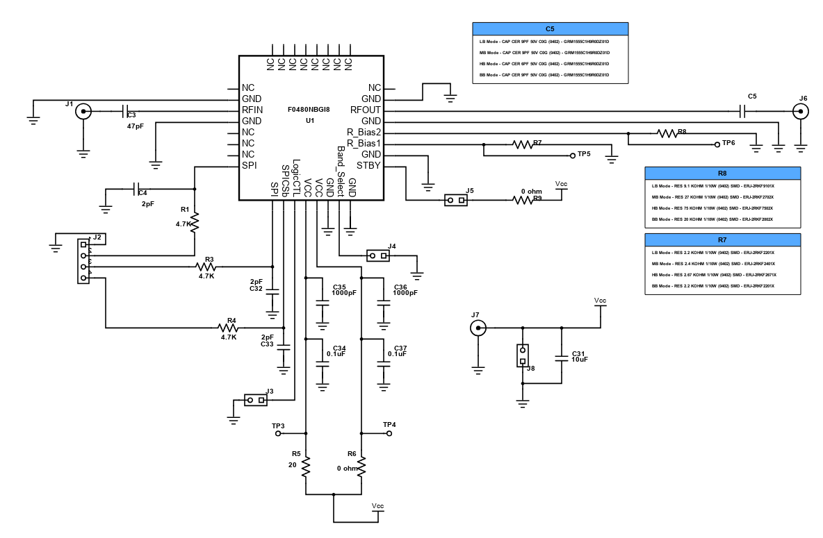
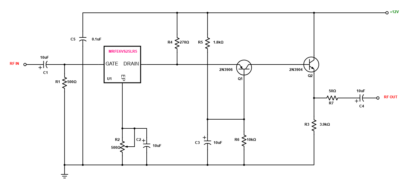
RF Amplifier Circuit
Radio-Frequency power amplifier converts a low power radio frequency signal into a significantly larger signal that is typically used for driving the antenna of a transmitter. Its output power usually measured in kilowatts which can be based on either solid state or vacuum tube technology. Most commercially manufactured linear amplifiers are used in amateur radio that provide between 10 to 20 times RF power amplification. Solid state linear amplifiers are more commonly in the 500 watt range and can be driven by as little as 25 watts.However, this design is a broadcast band RF amplifier that has a frequency response of up to 3MHz. It uses MRFE6VS25LR5 LDMOS transistor featuring a wide operating frequency range and enhanced ruggedness platform.
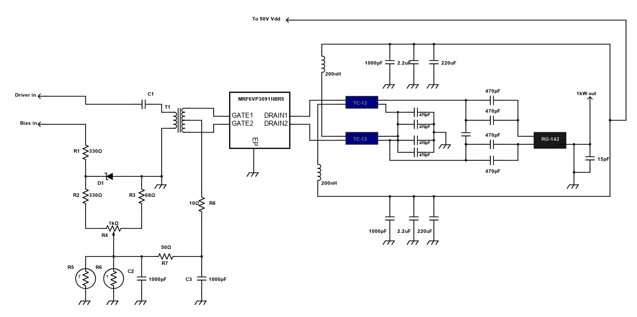
144 MHz, 1 kW Power Amplifier
This project is a simple solid state 1kW power amplifier that is used to read DC voltage and SWR on reverse/forward meters. The device has a watercooling that separates the transistor from the radiator. However, it automatically shuts down when the temperature is relatively high. This linear amplifier uses the Freescale's RF power LDMOS transistor that is capable of handling 10:1 VSWR and characterized with series equivalent large-signal impedance parameters. This can be used in single ended or in push pull configuration.
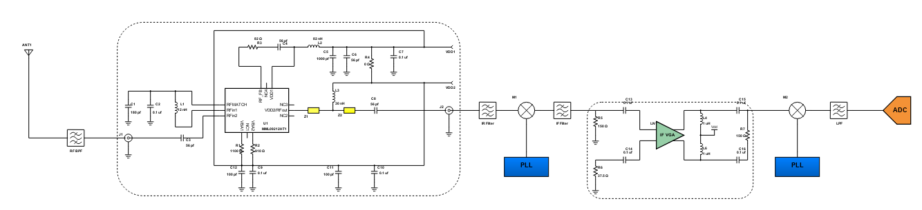
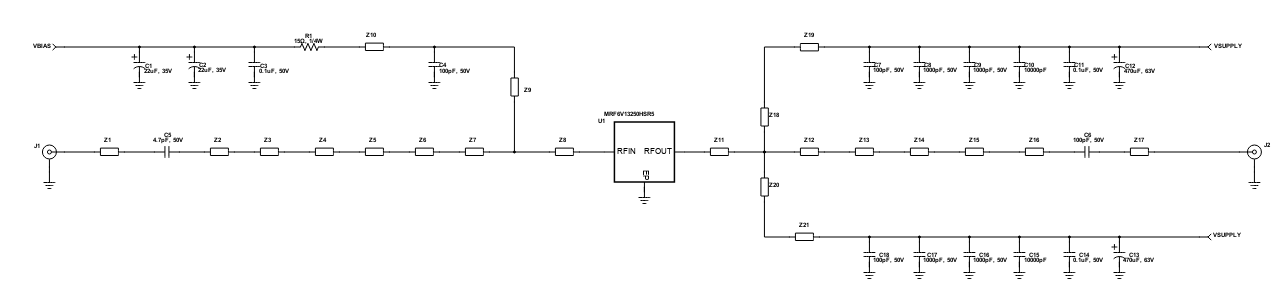
Commercial Aerospace L-band Amplifier
The aerospace communications provide us ease in data transmission and reception. It is now the ideal path to communicate around the world using wireless communications like mobile phones and other related gadgets. This design features an L-band test amplifier that ischaracterized with series equivalent large-signal impedance parameters. It has greater negative gate-source voltage range for improved class C amplifier operation. The system has also ESD protection incase of unexpected faults and surges. It can also handle up to 50V VDD supply during operation and it is internally matched for ease of use.
MC33904: System Basis Chip Gen2 with High Speed CAN
The System Basis Chip (SBC) is an integrated circuit that has a mixture of standard digital and analog functionalities, like communication bus interfaces and power functionality. The MCZ33903CP3EKR2 is part of the 33903/4/5 family, the second generation of Freescale's System Basis Chip (SBC). The device works for the MCU together with other integrated circuits such as sensors and CAN (Controller Area Network) transceivers as an advance power management unit. It is enhanced with a high speed CAN interface (ISO 11898 -2 and -5) with protection and fail-safe operation modes. This design also utilizes Freescale's SMARTMOS technology. The device features voltage, current, and temperature protection. It has an extremely low quiescent current in its low-power mode, a fully protected embedded 5.0V regulator for the CAN driver, and a configurable regulator for Serial Peripheral Interface (SPI). It is compatible to devices that support J2602-2 and LIN 2.1.
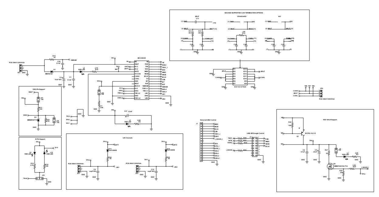
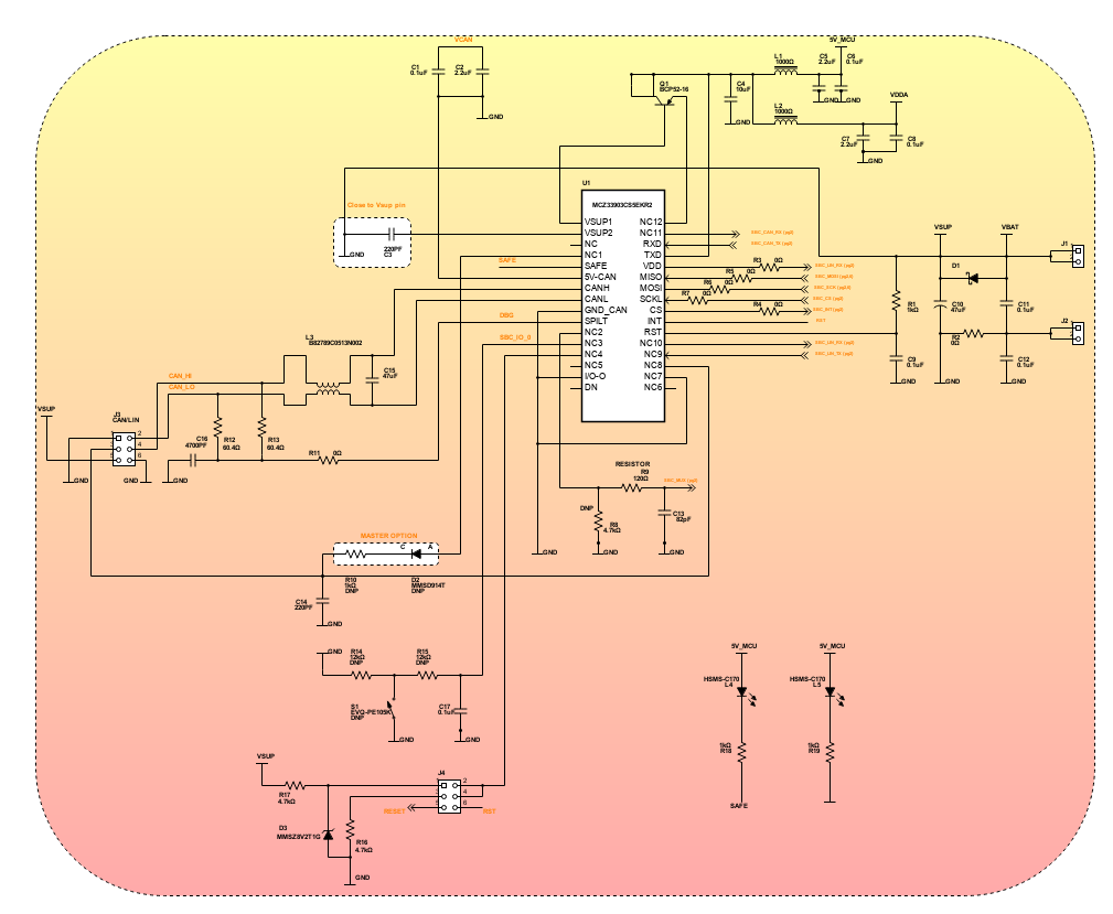
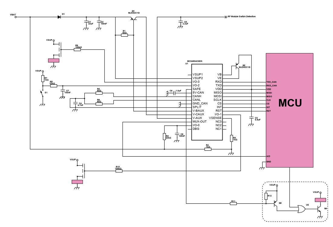
Power Management with System Basis Chip
This design is quite common to industrial application in which it helps to improve productivity of process control. It has fully protected embedded 5.0V regulator for the CAN driver and multiple undervoltage detections to address various MCU specifications and system operation modes. It is capable of multiple wake-up sources in LP modes such as CAN or LIN bus, I/O transition, automatic timer, SPI message, and VDD overcurrent detection. It is also ISO11898-5 high-speed CAN interface compatible for baud rates of 40kbps to 1Mbps.
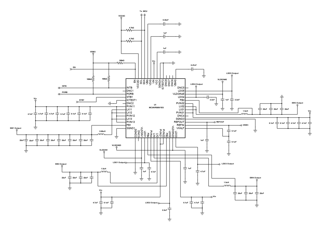
MC34VR500V1ES Multi-Output DC/DC Regulator
The circuit in this reference design features the capability of MC34VR500V1ES to supply multiple DC voltage outputs. This device is designed to support the LS1/T1 family of communication processors which require efficient and precise level of voltage supplies. With its four switching and five linear regulators, the MC34VR500V1ES can supply power to the whole system, e.g., the processor, memory, system peripherals.
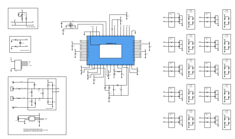
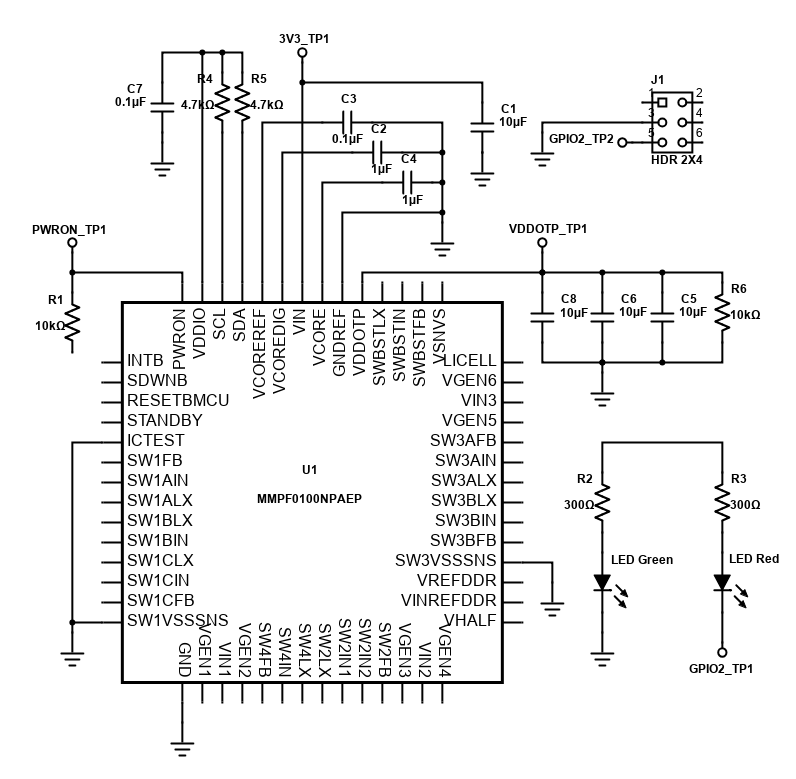
OTP Programming Socket for the PF Family of PMIC Devices
The reference design as shown is an KITPF0100SKTEVBE programming socket devices kit. The main function of the interface is to connect One-Time Programmable ICs using the KITPFPGMEVME programmer. It is a connector tool that features a QFN socket with 56 Pin which is used for programming the PF0x00 one-time programmable (OTP) registers in a stand alone PF0x00 parts using KITPFPGMEVME programmer. The KITPFPGMEVME programmer is a development design tool that aims to provide an easy configuration on the PF series devices. It also aims to facilitate prototyping and programming the device's OTP fuses.
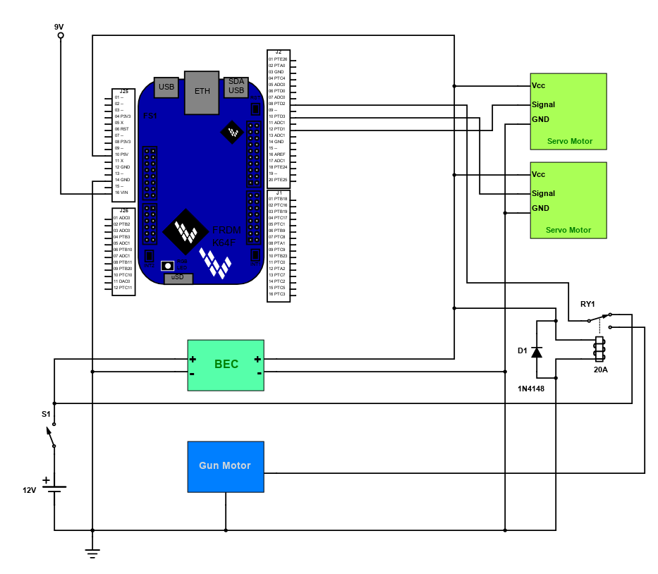
Nerf Gun using FRDMK64F
Nerf guns had completely overwhelmed people at all ages from the fact that pulling the trigger does not mean causing harm to anybody. It is an amazing project that anyone could easily practice their skills in shooting. This Nerf darts uses the Freescale's FRDM-K64F, an ultra-low-cost development platform that is packed with a lot of peripherals to enable rapid prototyping, including a 6-axis digital accelerometer and magnetometer to create full eCompass capabilities, a tri-colored LED and 2 user push-buttons for direct interaction and feedback, expansion memory with a microSD card slot, and connectivity options using onboard ethernet port and headers for use with bluetooth and 2.4GHz radio add-on modules.
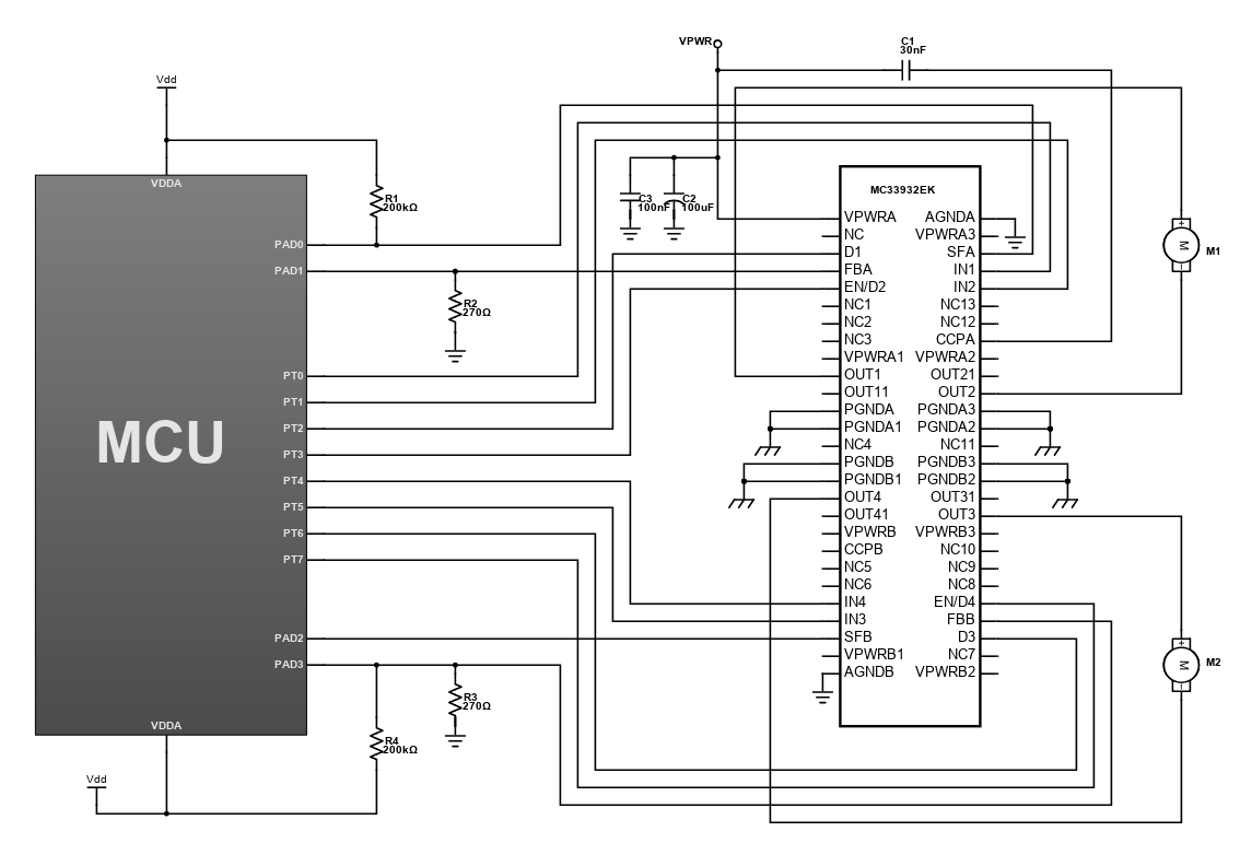
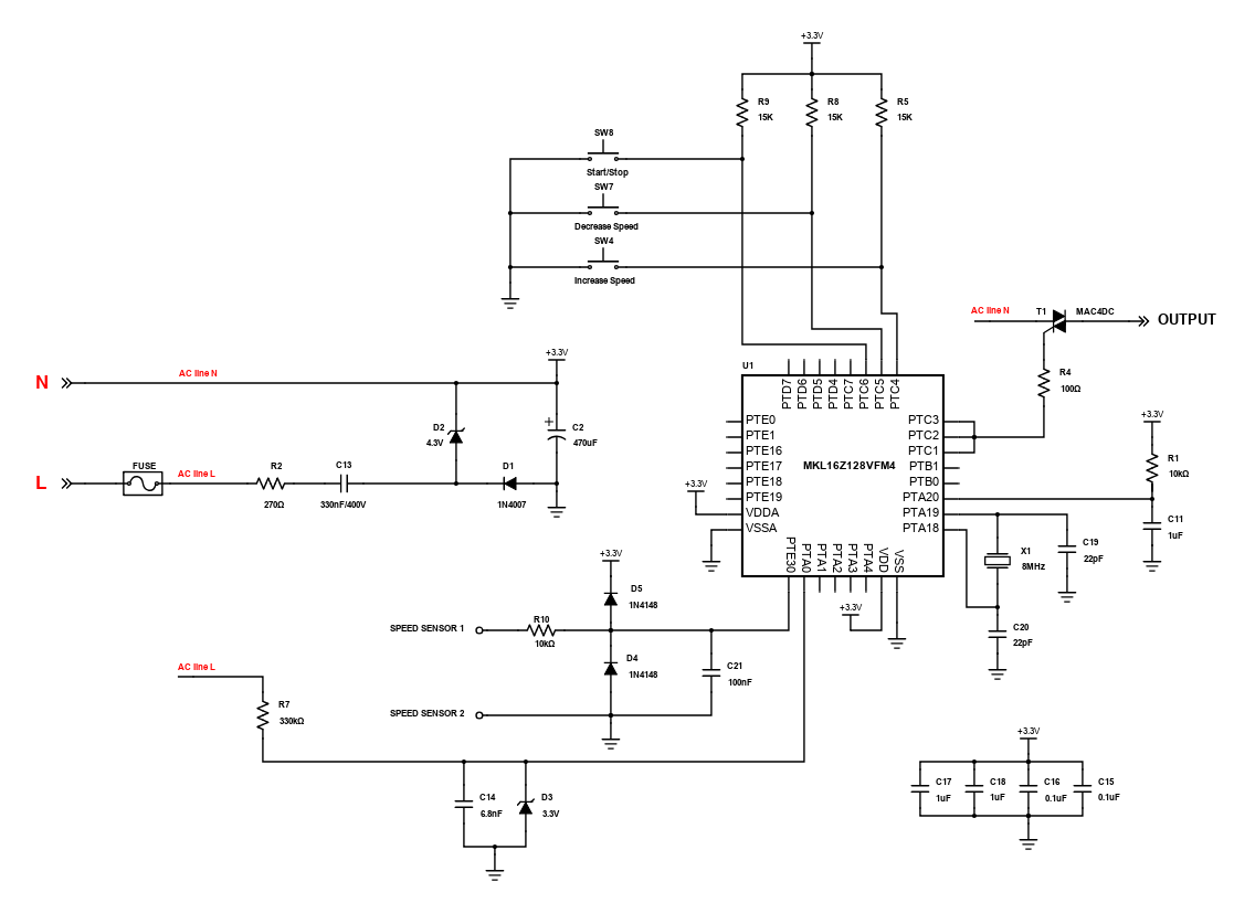
Phase Angle Motor Control
The reference design as shown is a phase angle control for universal motors. This circuit is used to control the speed of a universal motor. A universal motor is a commutated series wire-wound DC motor. This circuit uses phase angle control to vary the effective motor voltage. The basic principle of the phase angle control algorithm is simple: match the firing pulse time of the triac in relation with the zero crossing of the line voltage. A phase shift of this firing pulse produces a variable output voltage on the load. In this design, the microcontroller is used to control the triac. The snubberless triac is used as the power device. This triac has high dv/dt immunity: therefore, there is no need of RC circuit around it.
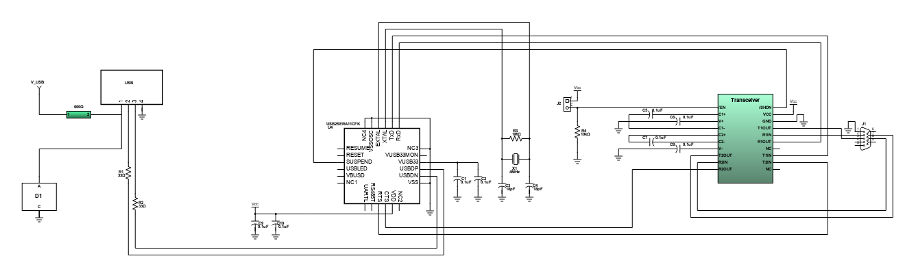
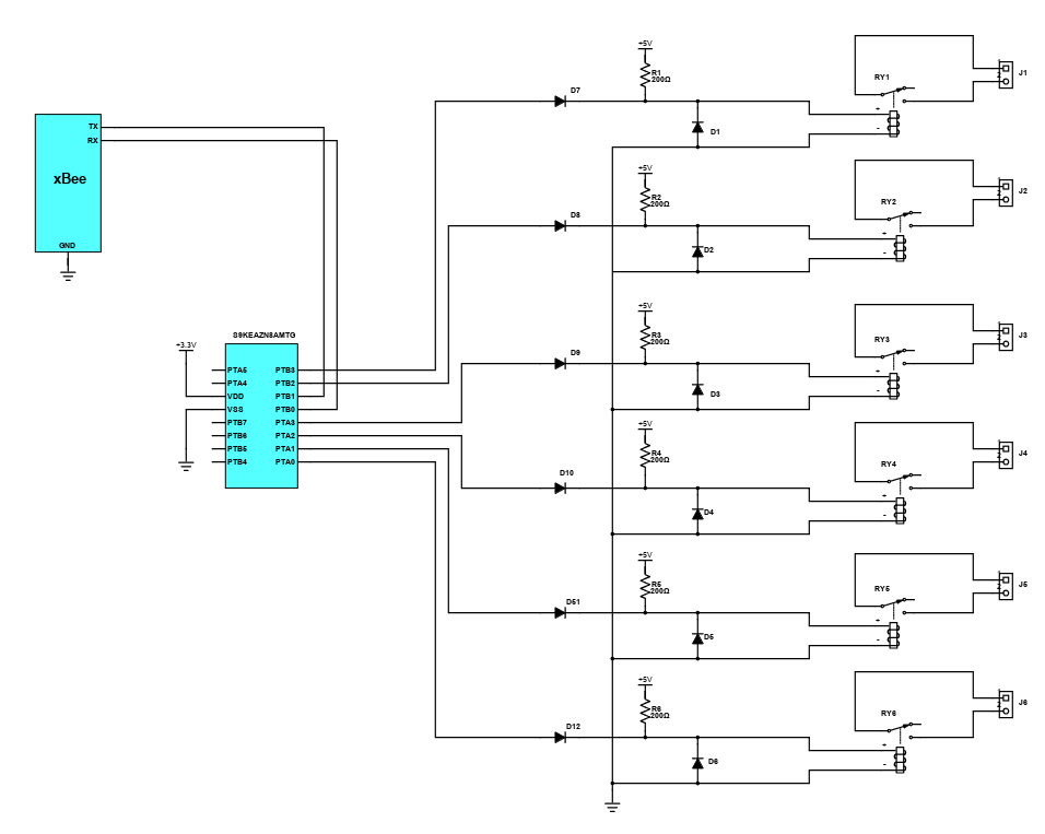
Generic Electronic Appliance Remote Control
The control of electronic appliances using wireless module before requires critical analysis. Making this as easy as possible innovates people to provide new ideas. The design is a straightforward circuit that contributes to the development of home automation, which is the remote control manipulation of electronic devices. The system is controlled by a 32-bit ARM Cortex MCU that supports up to two SPI modules, three UART modules, two IIC modules, and one CAN module. It is energy efficient and durable even for industrial applications that requires the highest level of quality and longevity support.
Introduction
Schematic Drawings
Use schematic symbols to layout the components of your circuit and make electrical connections. With symbols ranging from amplifiers to vacuum tubes, as well as the ability to build custom symbols, you are able to design nearly any circuit. Access to Digi-Key's extensive part database also allows you to browse and assign orderable part numbers.
Diagram Building
Use the system blocks to refine your idea at a conceptual level. The higher-level components are there to help you plan out the broader intentions of your idea. This powerful block chain library allows you to quickly layout the function of circuit. Once your design is ready, save and share with your colleagues.
Flow Chart Creation
The flow chart creation option will help transition your concept to a design. Use the library of arrows, shapes, UML symbols, and more to sort out the flow and annotate each stage. Insert a textbox, math function/formula, image, or link to help illustrate the objectives and make your plan easy to follow.
Help & Resources
Need help? Ask questions in our TechForum

Conversion Calculators
Digi-Key's online conversion calculators offer a one-stop resource for many electronics industry calculations.
Go to Calculators
Conversion Calculators
Digi-Key's online conversion calculators offer a one-stop resource for many electronics industry calculations.
Go to Calculators

Reference Design Library
Search for designs based on the circuit's performance using Digi-Key's Reference Design Library.
Go to Reference Design Library
Reference Design Library
Search for designs based on the circuit's performance using Digi-Key's Reference Design Library.
Go to Reference Design Library
Tech Forum
Feedback
You are about to delete project
Please type 'DELETE' (without quotes) to the below box to confirm the deletion: