Scheme-it
Introduction
Schematic Drawings

Use schematic symbols to layout the components of your circuit and make electrical connections. With symbols ranging from amplifiers to vacuum tubes, as well as the ability to build custom symbols, you are able to design nearly any circuit. Access to Digi-Key's extensive part database also allows you to browse and assign orderable part numbers.
Diagram Building

Use the system blocks to refine your idea at a conceptual level. The higher-level components are there to help you plan out the broader intentions of your idea. This powerful block chain library allows you to quickly layout the function of circuit. Once your design is ready, save and share with your colleagues.
Flow Chart Creation

The flow chart creation option will help transition your concept to a design. Use the library of arrows, shapes, UML symbols, and more to sort out the flow and annotate each stage. Insert a textbox, math function/formula, image, or link to help illustrate the objectives and make your plan easy to follow.
Projects
Design Starters help give you a running start for your next design. Whether you are looking to begin a wireless charging platform or quickly design around a Bluetooth Low Energy module, our Design Starters will help get you quickly on your way.
Digi-Key has worked with industry leaders to help drive almost instantaneous ideation and these starters are ideal building blocks to help get your concepts created, drawn and documented in almost no time at all. Featured Design Starters
12 items
Refine Search
APPLICATION
MANUFACTURER
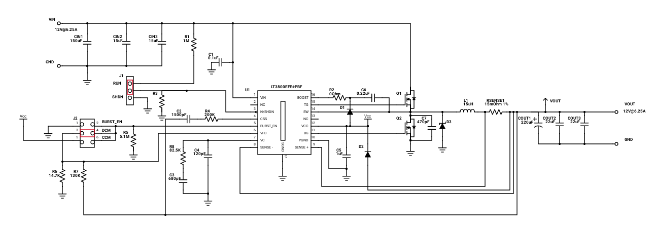
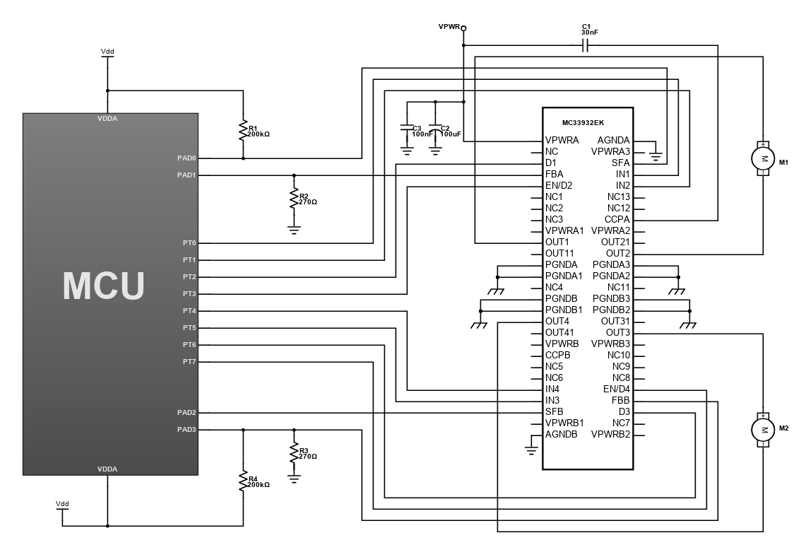
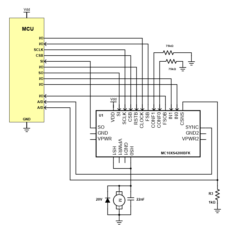
Dual High Side Switch Motor Control
This design is a simple motor control that uses the Freescale's MC10XS4200BFK dual high side switch. It has two fully protected 10mΩ high side switches with up to 6A steady state current per channel. Both channels can be controlled individually by external or internal clock signals, or by direct inputs. In addition, it has an accurate temperature and current sensing and has individually programmable internal/external PWM clock signals that allow fully autonomous device operation.
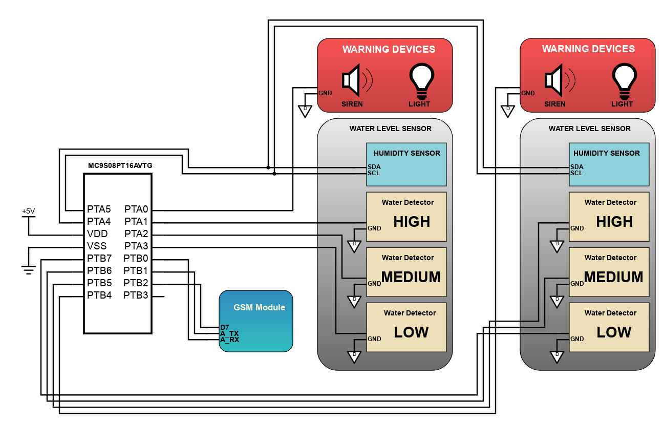
Flood Level Monitor
The factors that cause floods have been constantly increasing and as a result, flooding has become frequent and hazardous especially in low level areas. This design features a flood level monitor that measures rainfall intensity and flood level, and automatically alerts the community and relevant authorities of the measured data using a GSM module and other warning devices.
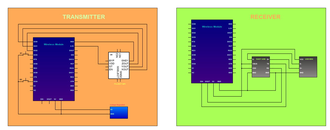
Wireless Tilt Mouse
Wireless tilt mouse allows the control of mouse cursor on the PC screen through tilting of the board. It specifically uses the Freescale's FXLN8371QR1 accelerometer, which is a family of 3-axis, low-power, low-g, analog output accelerometers that consist of an acceleration sensor along with a CMOS signal conditioning and control ASIC in a 3x3x1 mm QFN package. The analog outputs for the X, Y, and Z axes are internally compensated for zero-g offset and sensitivity, and then buffered to the output pads. The outputs have a fixed zero-g offset of 0.75V, irrespective of the VDD supply voltage. The bandwidth of the output signal for each axis may be independently adjusted using external capacitors. This handheld mouse device measures its tilt and then wirelessly transmits the data to a base unit. It is connected to a PC through a USB cable and can be recognized by certain modern computers as an actual mouse.
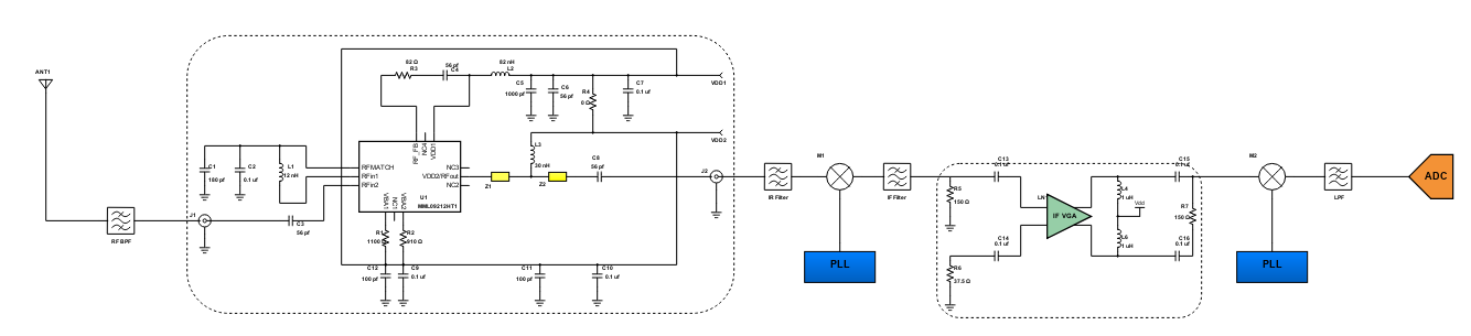
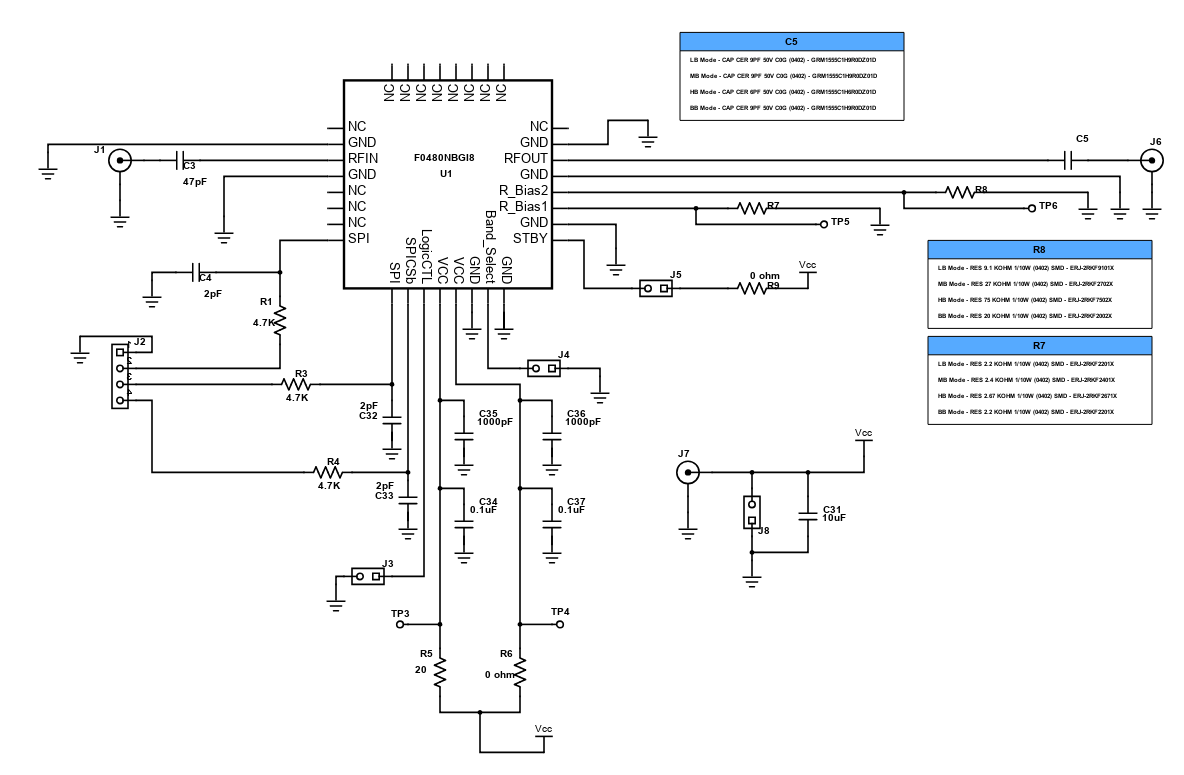
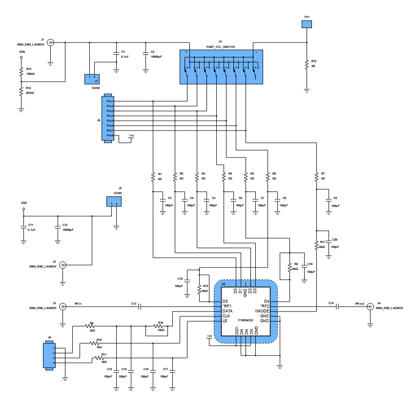
2500MHz Linear Amplifier using MMA25312BT1 InGap HBT
Ideally, an amplifier is said to be linear if the input power is proportionally related to the output power by the gain of the amplifier. In an RF amplifier design, linearity is a very important parameter to be considered since it determines the fidelity of the signal. High amplifier linearity is possible, but at the expense of efficiency. One of the classic trade offs in power amplifier transistors is between output power and bandwidth. Active devices are inherently limited in bandwidth by internal capacitance. Eventually, every transistor reaches a frequency at which signal gain drops below unit and where the device is no longer useful as an amplifier. Smaller transistor geometries can achieve higher operating frequencies, but the smaller dimensions result in reduced power capacity.

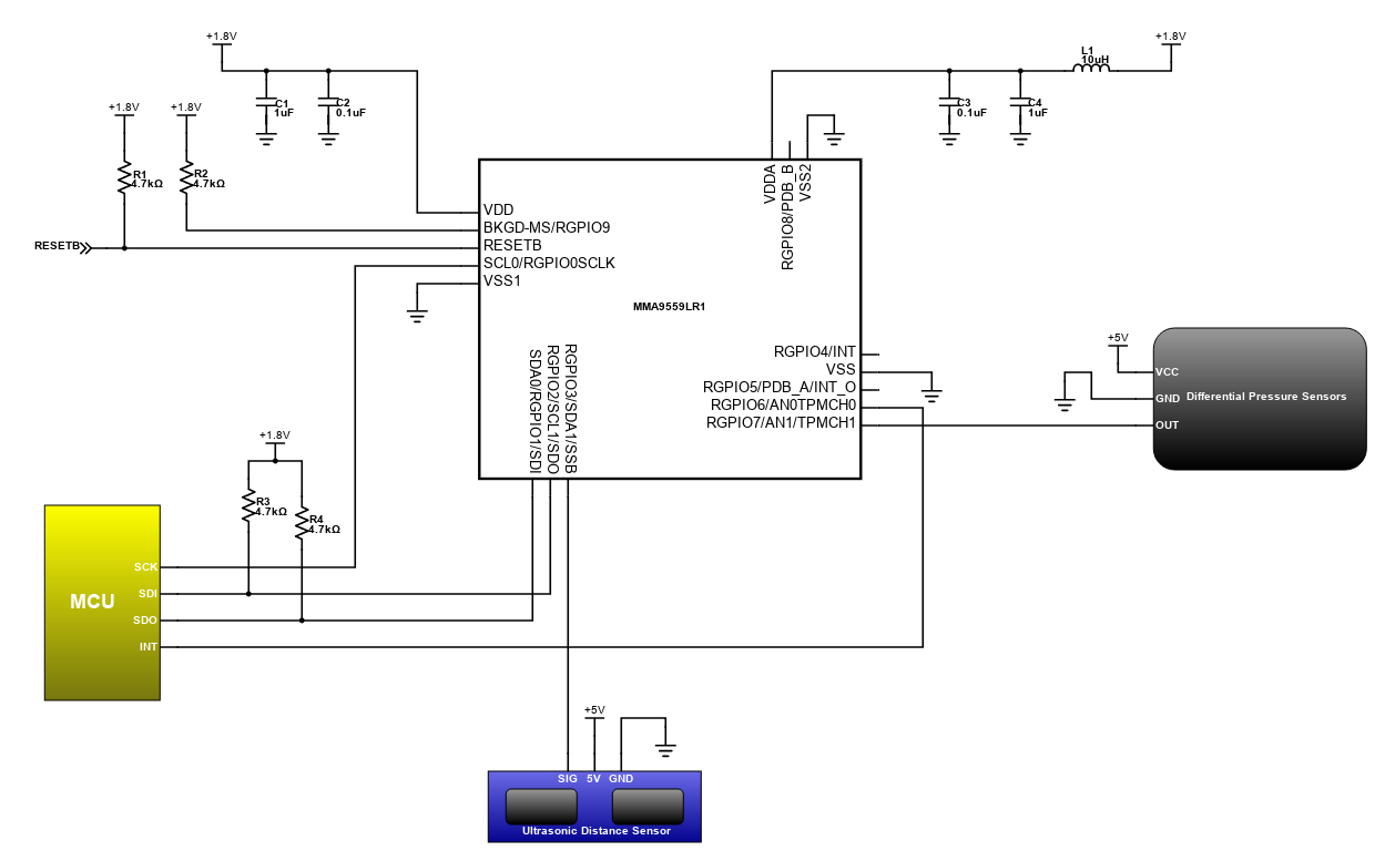
Industrial Process Multipurpose Monitoring Unit
There are several manufacturing plants invested to systems upgrade particularly in the production side. Instead of deploying a lot of operators in the production, the company invested to several types of automation that increases monitoring efficiency. This improvement in the industry attracted more investors that compensate to the employment losses. This design features a highly integrated system that optimized the sensing applications. It has three accelerometers that operate in different ranges with integrated temperature sensor. It can monitor pressure and object distance through the interfaced sensors. There are eight selectable output data rates from 488Hz to 3.8Hz and four types of trimmed ADC data formats such as 10, 12, 14, and 16-bit. The system has also ROM-based flash controller and slave port, command-line interpreter for some embedded purposes.
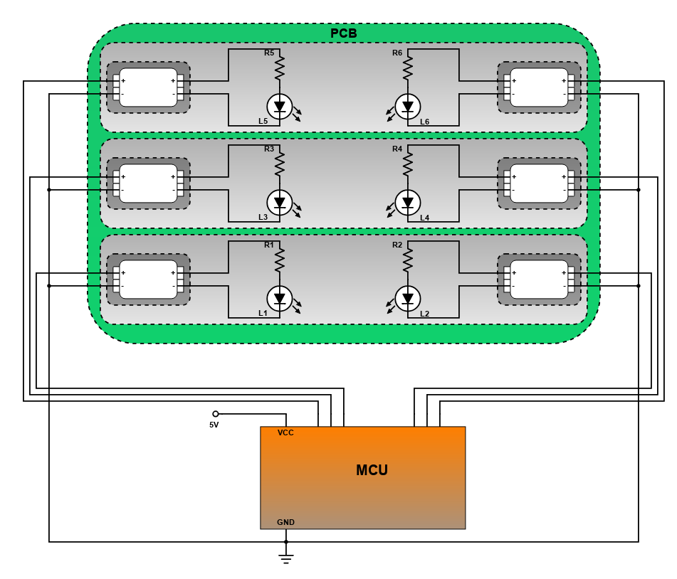
Blinking LEDs using LED Demo Board with SMT Releasable Poke-In Connectors
This circuit diagram shows an MCU-based blinking LED project using the LED demo board with Low Profile SMT Releasable Poke-In Connectors. LED lighting, nowadays, has lit up the electronics industry in terms of growth. It has replaced the incandescent bulbs as well as the compact fluorescent lamp (CFL). This is because LEDs have a lower rated power and longer lifespan as compared to the incandescent bulb and CFL.
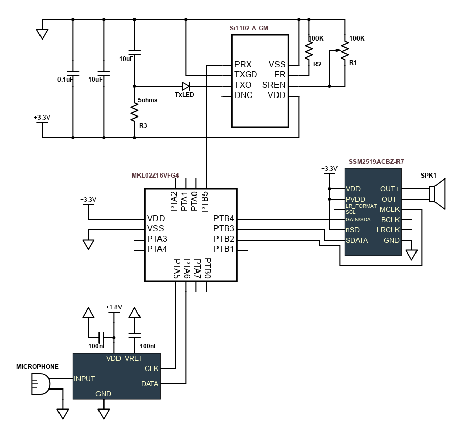
Digital Hearing Aid using MKL02Z16VFG4
A hearing aid is a small electronic device worn in or behind the ear that amplifies incoming sounds to help people with hearing impairment. This design features a light and compact hearing aid with a soft touch sensor that allows the user to control the volume and frequency depending on the user's preference.
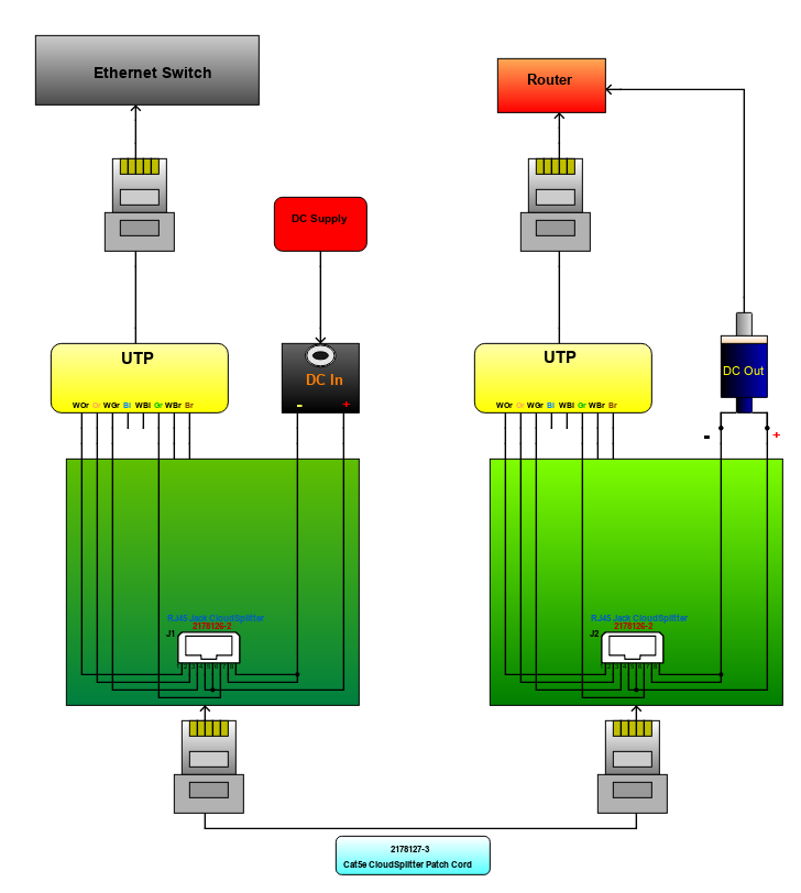
Power Over Ethernet Adapter
The Power Over Ethernet (PoE) is a technology used for transmitting power to equipments in a network, using ethernet cables. This PoE is very advantageous, especially when connecting to equipments that are far from power sources. It also offers benefits such as time and cost saving, flexibility, safety, reliability and scalability. Today, the new network equipments are already having built-in PoE features. For non-PoE capable devices, they use the PoE Adapter.
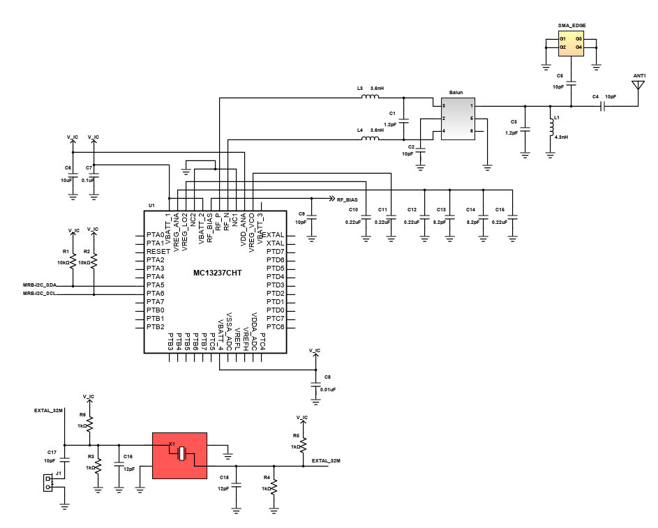
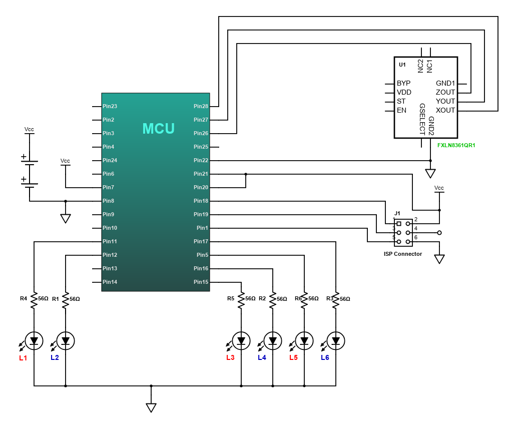
Interfacing an Accelerometer with an AVR microcontroller
The capabilities of this project on measuring acceleration and orientation in space are described using Freescale's 3-axis FXLN8361QR1 xtrinsic accelerometer interfaced with a microcontroller. Accelerometers are recently developed solid-state electronics devices that makes it very easy to measure acceleration. They are completely modular and very tiny devices, which gives voltage proportional to acceleration. These types are called analog accelerometers, as their output is voltage. While other gives a PWM output or direct binary digital data, they are called digital accelerometers.
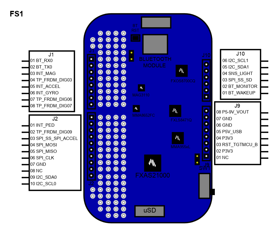
KIT FRDM-K64F FRDM-FXS-MULTI-B - FRDM-SFUSION
The FRDM-SFUSION sensor fusion development kit brings together the FRDM-SFUSION sensor fusion software library with Freedom development boards for application development and rapid prototyping. This kit makes it easy to bring your next sensor-based design to life and offers premium grade support when you need it.
The sensor fusion development kit (FRDM-SFUSION) includes:
- FRDM-K64F Freedom development board for Kinetis K64, K63, and K24 MCUs
- FRDM-FXS-MULTI-B Freedom development board for sensors (Bluetooth)
- Sensor fusion software library (download)
Introduction
Schematic Drawings
Use schematic symbols to layout the components of your circuit and make electrical connections. With symbols ranging from amplifiers to vacuum tubes, as well as the ability to build custom symbols, you are able to design nearly any circuit. Access to Digi-Key's extensive part database also allows you to browse and assign orderable part numbers.
Diagram Building
Use the system blocks to refine your idea at a conceptual level. The higher-level components are there to help you plan out the broader intentions of your idea. This powerful block chain library allows you to quickly layout the function of circuit. Once your design is ready, save and share with your colleagues.
Flow Chart Creation
The flow chart creation option will help transition your concept to a design. Use the library of arrows, shapes, UML symbols, and more to sort out the flow and annotate each stage. Insert a textbox, math function/formula, image, or link to help illustrate the objectives and make your plan easy to follow.
Help & Resources
Need help? Ask questions in our TechForum

Conversion Calculators
Digi-Key's online conversion calculators offer a one-stop resource for many electronics industry calculations.
Go to Calculators
Conversion Calculators
Digi-Key's online conversion calculators offer a one-stop resource for many electronics industry calculations.
Go to Calculators

Reference Design Library
Search for designs based on the circuit's performance using Digi-Key's Reference Design Library.
Go to Reference Design Library
Reference Design Library
Search for designs based on the circuit's performance using Digi-Key's Reference Design Library.
Go to Reference Design Library
Tech Forum
Feedback
You are about to delete project
Please type 'DELETE' (without quotes) to the below box to confirm the deletion: