Scheme-it
Introduction
Schematic Drawings

Use schematic symbols to layout the components of your circuit and make electrical connections. With symbols ranging from amplifiers to vacuum tubes, as well as the ability to build custom symbols, you are able to design nearly any circuit. Access to Digi-Key's extensive part database also allows you to browse and assign orderable part numbers.
Diagram Building

Use the system blocks to refine your idea at a conceptual level. The higher-level components are there to help you plan out the broader intentions of your idea. This powerful block chain library allows you to quickly layout the function of circuit. Once your design is ready, save and share with your colleagues.
Flow Chart Creation

The flow chart creation option will help transition your concept to a design. Use the library of arrows, shapes, UML symbols, and more to sort out the flow and annotate each stage. Insert a textbox, math function/formula, image, or link to help illustrate the objectives and make your plan easy to follow.
Projects
Refine Search
DATE RANGE
13022020
2020-02-13 09:28:13
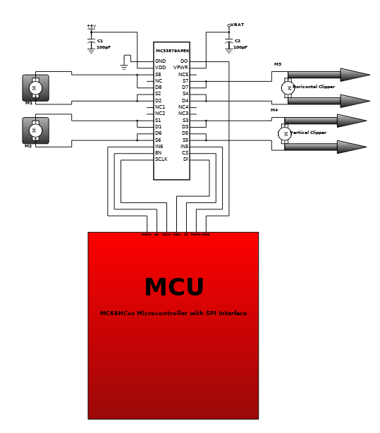
The design is comprised of MC33879APEK configurable octal serial switch with open load detect current disable and incorporates SMARTMOS technology. It is used to control the dc motors that are interfaced to the system. The 5V supply and VBAT are provided with capacitor filters. The dc motors are placed to the different parts of the robot. The platform revolute is installed at the surface so the robotic arm itself can rotate horizontally (azimuth movement). The arm revolute is installed directly above the platform so the robot can rotate vertically (elevation movement). The horizontal and vertical clipper serves as the fingers of the robot that will have direct contact to the target object. The MCU or microcontroller unit is used as a host controller of the system and it also processes the robot data input/output. The design is applicable to robotic development with design considerations. It is applicable to different types of dc motors assuming that the power requirements are met. The design is flexible that only few modifications required so it can be used for other applications.
prod test 0910
2020-02-13 02:16:03
The circuit has a frequency response of up to 3 MHz with a gain that is about 30 dB. Field-effect transistor Ql is configured in the common-source self-biased mode; optional resistor R1 allows you to set the input impedance to any desired value. Commonly, it will be 50 . The signal is then direct-coupled to Q2, a common-base circuit that isolates the input and output stages and provides the amplifier`s exceptional stability. Last, Q3 functions as an emitter-follower, to provide low output impedance (about 50 ).If you need higher output impedance, include resistor R8. It will affect impedance according to this formula: Rs ~ ^0lJT - 50. Otherwise, connect output capacitor C4 directly to the emitter of Q3. This design is used in telecommunication system with frequency range of 1.8MHz to 2000MHz. Its basic applications include driving to another high power source, driving a transmitting antenna, microwave heating, and exciting resonant cavity structures. Among these applications, driving transmitter antennas is most well known. The transmitter–receivers are used not only for voice and data communication but also for weather sensing in the form of a RADAR.

12022020-designer-starter-test
2020-02-12 10:17:42
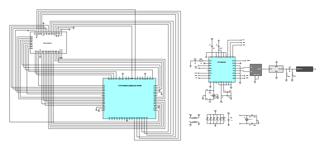
This ZigBit module contains Atmel's ATxmega256A3U Microcontroller and AT86RF233 2.4GHz ISM band Transceiver for ZigBee and IEEE 802.15.4 [1]. The module features 256KB in-system self-programmable Flash memory, 16KB SRAM and 4KB EEPROM. The compact all-in-one board design of MCU and radio transceiver with very minimal components on the RF path to Antenna dramatically improves the ZigBit's compact size, range performance on signal transmission and increases its sensitivity. This ensures stable connectivity within a larger coverage area, and helps develop applications on smaller footprint. The MS-147 connector [2] can be used as an RF Test port. ZigBit Module contains a complete RF/MCU design with all the necessary passive components included. The module can be easily mounted on a simple 2-layer PCB with a minimum of required external connection. The ZigBit Module evaluation kit containing the ZigBit extension board for the Atmel Xplained PRO HW evaluation platform can be used to develop FW using the Atmel Studio and evaluate using the Wireless Composer. Compared to a custom RF/MCU solution, a module-based solution offers considerable savings in development time and NRE cost per unit during the HW/FW design, prototyping, and mass production phases of product development. All ZigBits are preloaded with a bootloader when they are sold as modules, either in single units or T&R. Depending on end-user design requirements, the ZigBit can operate as a self-contained sensor node, where it would function as a single MCU, or it can be paired with a host processor driving the module over a serial interface. The Zigbit module has various applications such as for building automation and monitoring, HVAC monitoring, inventory management, environmental monitoring, security and any other related industrial monitoring.
20200212 Gloves Wireless USB Gesture Input System
2020-02-12 10:11:44
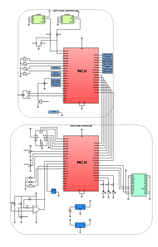
This reference design is a wireless USB gesture input system that enables a person to use a computer by performing intuitive hand and finger motions in the air. While wearing a glove controller on the right hand, the user can move the cursor by forming a pointing gesture and click by curling the index finger or thumb. Other right hand gestures enable scrolling and provide access to various keyboard shortcuts. Wearing a glove device on the left hand allows the user to type different keys through a combination of tilting the hand and touching different portions of the palm and fingers with the thumb. The left and right controllers are attached to each other but communicate to the computer wirelessly through a base station. Mister Gloves uses a low-speed USB 1.1 interface and does not require the installation of additional drivers. Freescale Semiconductor's MMA1260D, MMA2260D and FXLN8361QR1 accelerometers are used in this design. These sensors measure acceleration due to gravity in the Z-axis and X-axis, respectively, and give an analog output. These sensors are aligned such that their acceleration vectors are orthogonal and both lie in the plane of the left hand. Pointing the acceleration vector towards ground results in a higher output voltage and vice versa. This design is applicable to commercial products, hobby projects, and other fields that involve gesture recognition.
2020-02-12T03:37:26+00:00_USB Tilt Module
2020-02-11 21:37:30
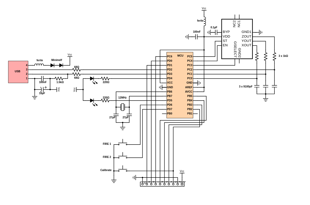
The self calibration mode has been added to allow for easy calibration without a special software tool running on the host; Press and hold the calibration button on the device for at least three seconds until the green LED turns off. The yellow calibration LED will then start blinking once a second to indicate that step one of the "self calibration" is in progress. Hold the device "flat" and press the calibration button again within 15 seconds. The yellow LED will start flashing twice each second to indicate that this was successful and that the second step of the calibration is to be performed. Tilt the device 90 degrees to the right and again press the calibration button within 15 seconds. The LED will start blinking three times each second. Tilt the device 90 degrees down and once more press the calibration button within 15 seconds. The LED will start blinking four times each second. Press the calibration button one last time within 15 seconds to permanently store the new calibration data inside the sticks internal EEPROM memory. The yellow LED will stop flashing and the green LED will turn on again. Calibration is done!
The accelerometers used on the device need to be calibrated in order to get accurate measurements in the range of -2G to +2G and to adjust the layout of the two axes to e.g. cope with the fact that the device may be oriented differently when attached to different host computers. The device can be used in conjunction with any software that can be controlled using a simple two axis joystick with two fire buttons, however, the device is not a joystick.
Introduction
Schematic Drawings
Use schematic symbols to layout the components of your circuit and make electrical connections. With symbols ranging from amplifiers to vacuum tubes, as well as the ability to build custom symbols, you are able to design nearly any circuit. Access to Digi-Key's extensive part database also allows you to browse and assign orderable part numbers.
Diagram Building
Use the system blocks to refine your idea at a conceptual level. The higher-level components are there to help you plan out the broader intentions of your idea. This powerful block chain library allows you to quickly layout the function of circuit. Once your design is ready, save and share with your colleagues.
Flow Chart Creation
The flow chart creation option will help transition your concept to a design. Use the library of arrows, shapes, UML symbols, and more to sort out the flow and annotate each stage. Insert a textbox, math function/formula, image, or link to help illustrate the objectives and make your plan easy to follow.
Help & Resources
Need help? Ask questions in our TechForum

Conversion Calculators
Digi-Key's online conversion calculators offer a one-stop resource for many electronics industry calculations.
Go to Calculators
Conversion Calculators
Digi-Key's online conversion calculators offer a one-stop resource for many electronics industry calculations.
Go to Calculators

Reference Design Library
Search for designs based on the circuit's performance using Digi-Key's Reference Design Library.
Go to Reference Design Library
Reference Design Library
Search for designs based on the circuit's performance using Digi-Key's Reference Design Library.
Go to Reference Design Library
Tech Forum
Feedback
You are about to delete project
Please type 'DELETE' (without quotes) to the below box to confirm the deletion: